JOHN'S RADIO-ELECTRONICS PAGE
COMPENDIUMS, MANUALS, SCHEMATICS, AND DIY PROJECTS
CREATED: 3/23/2016
JuLY 2024 UPDATE
ANNOUNCEMENTS
1. I bought a Hallicrafters Hurricane without its factory power supply at an auction site and I've been acquiring the parts necessary
to build my own high-voltage, high power supply for it. I've also been building adapters to test RF tubes like the 8072 and 8122 on
standard tube testers. I'm also still working on that '89 Iroc Z. I have too many irons in the fire right now. I also need to re-design
this web site to make it more compact.
The power supply is finished and it works! Scroll down to go right to the section.
2. I sold the Collins KWM-2 that I won on eBay. I just don't have time to get into a long-term project with it, and I lacked an
actual Collins power supply. I built an adapter cable to power it using a Swan 117XC power supply. The cable was and easy build.
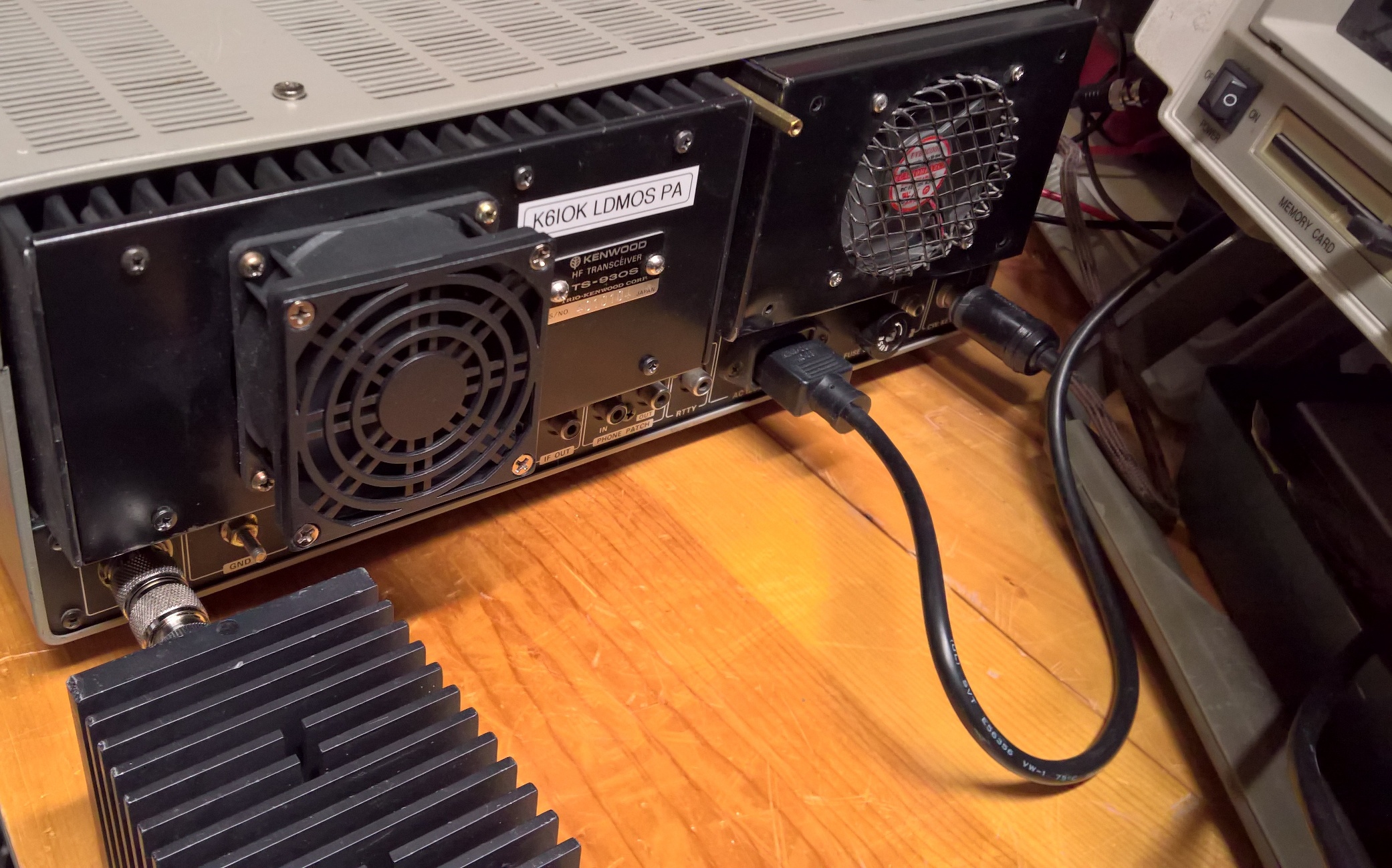
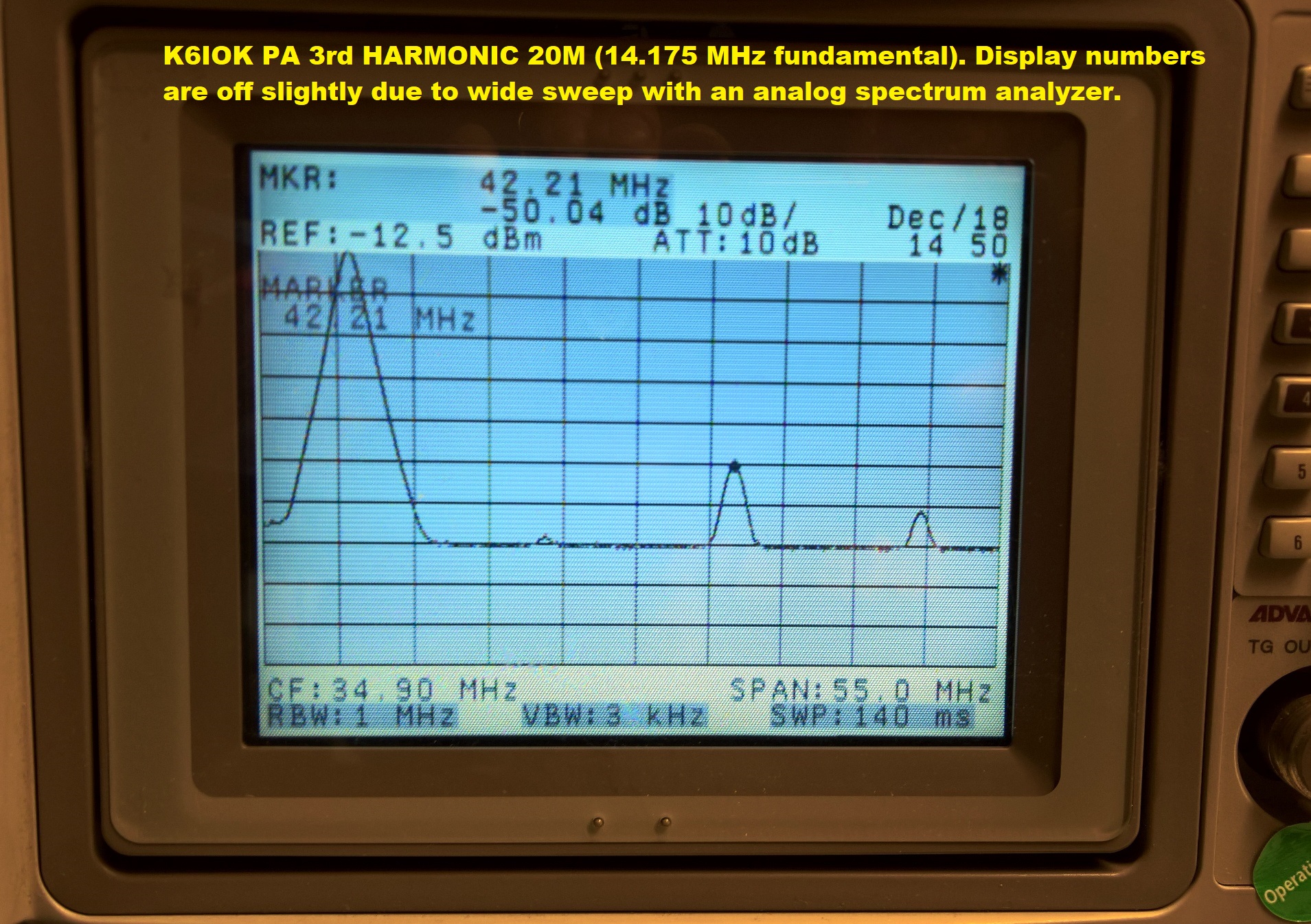
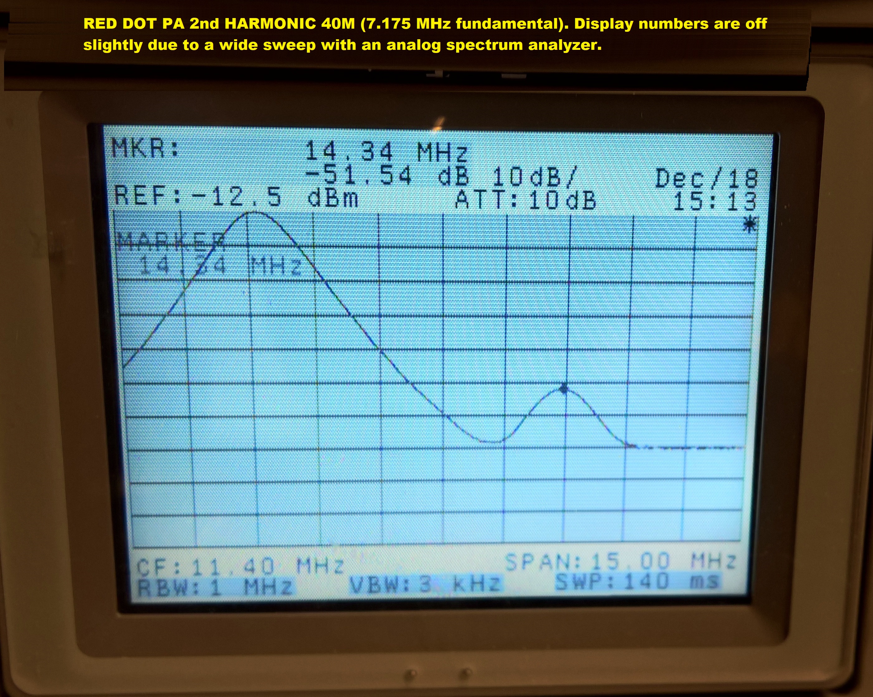
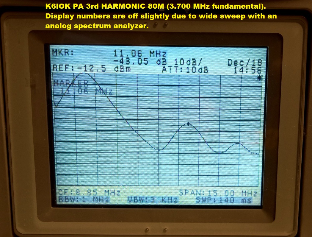
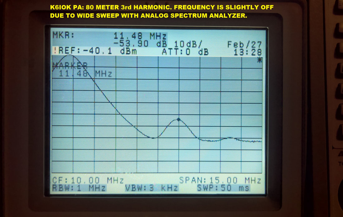
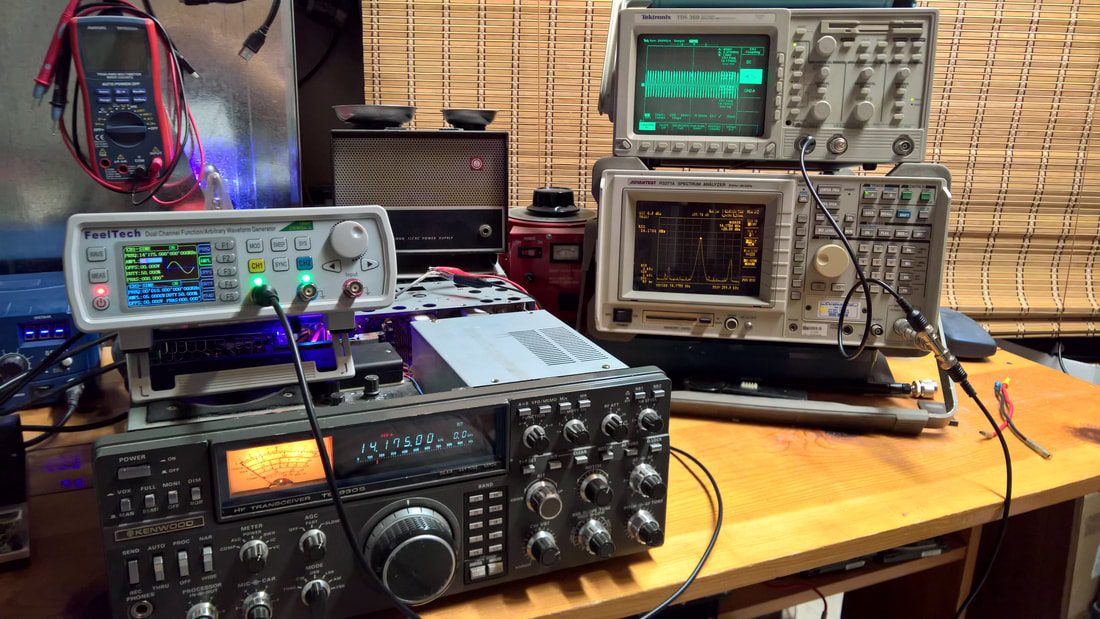
3. I've tested the K6IOK and a Red Dot PA using a 100 watt, 30dB attenuator by running the output of my TS-930S test bed
radio directly to my spectrum analyzer for harmonic testing. This setup yielded much better results for both PA's.
Apparently, something in my previous test setup was influencing the results.
4. The RF input voltages vs power output table in the button labeled "APPROX POWER OUTPUT FROM PA AT VARIOUS RF
LEVELS" are too high. I recently discovered that the little FeelTech RF waveform generator that I used can't handle a
50-ohm load. The RF voltages are about 2X too high. I'll redo the paper and chart eventually.
to build my own high-voltage, high power supply for it. I've also been building adapters to test RF tubes like the 8072 and 8122 on
standard tube testers. I'm also still working on that '89 Iroc Z. I have too many irons in the fire right now. I also need to re-design
this web site to make it more compact.
The power supply is finished and it works! Scroll down to go right to the section.
2. I sold the Collins KWM-2 that I won on eBay. I just don't have time to get into a long-term project with it, and I lacked an
actual Collins power supply. I built an adapter cable to power it using a Swan 117XC power supply. The cable was and easy build.
3. I've tested the K6IOK and a Red Dot PA using a 100 watt, 30dB attenuator by running the output of my TS-930S test bed
radio directly to my spectrum analyzer for harmonic testing. This setup yielded much better results for both PA's.
Apparently, something in my previous test setup was influencing the results.
4. The RF input voltages vs power output table in the button labeled "APPROX POWER OUTPUT FROM PA AT VARIOUS RF
LEVELS" are too high. I recently discovered that the little FeelTech RF waveform generator that I used can't handle a
50-ohm load. The RF voltages are about 2X too high. I'll redo the paper and chart eventually.
in memory of jeff bodin, wa0vom - see tab two.
harmonics testing - ts-930s pa's
The text below is word-for-word from Rhode & Schwartz's excellent Application Note titled Measurement of Harmonics using Spectrum Analyzers:
"One of the key features of non-linear elements in any electronic circuit is the generation of harmonic signals. On the one hand side, harmonics resulting from the non-linear characteristic of a given component like a diode, are used intentionally to implement vital functions for today’s RF world, such as e.g. harmonic mixers. On the other hand, not every harmonic signal generated by a DUT may be welcome. In an ideal world, amplifiers do not generate any harmonics, but simply amplify the input signal. One of the challenges in the real world therefore is to optimize a device to come as close as possible to its ideal, which means to make use of the wanted harmonics (e.g. of 3rd order) and suppress the unwanted harmonics (e.g. of 2nd order). When it comes to measuring the harmonics of a device, not only the device under test (DUT) consists of non-linear elements. The measuring instrument - usually a spectrum
analyzer – contains amplifiers and mixers, which also may generate harmonics and thus contribute to the measurement results. During the verification of the harmonic specifications of a DUT, extra effort therefore is necessary to differentiate harmonics
generated by the DUT from harmonics generated by the measuring instrument."
I lack some of the equipment shown in their Application Note and also used during the creation of Part 97, but my intent here was to compare two amps side-by-side under the kind of conditions found in a typical HAM shack. For instance, one criteria for the testing is that the fundamental be removed from the signal using a band pass filter so that it won't be present along with the harmonics during testing. But that's NOT they way it will happen in your shack. The Fundamental and the harmonics will be all mixed together and sent out over your output line to the antenna. So that's how I tested the amps - full output at 100W output right to my Spectrum Analyzer. I bought a used Bird 30dB attenuator because quality is important here. A cheap attenuator might send 50 - 100 watts into my SA and fry the input amp. That would make Jack (me) a very mad boy!
So here are some images of my tests. UNDER CONSTRUCTION - MORE TO COME
So here are some images of my tests. UNDER CONSTRUCTION - MORE TO COME


SWAN 1200-W CORRECTIONS. An astute reader (Matt - W0MBW) noticed an error in the schematic for the SWAN/CYGNET 1200-W schematic, and it's repeated on the 1200-X schematic also. Corrected diagrams are below in the SWAN section.
Two buttons have been added below that shows the approximate power output from a TS-930S and a 940S power amplifier at various input voltage levels. One is in RF volts (mine) which was derived by disconnecting the RF input lead from the Signal Unit DRV terminal and watching the RF output, and the other, which is for the identical 940S PA is more technical. It's from Dave Phillips, who has probably forgotten more about repairing the Kenwood 930 & 940S than I'll ever know. His is in dBM, watts, RF volts, and dBuV, measured with his Rigol Spectrum Analyzer. I'll have to try that approach with my new Advantest SA.
CASE HISTORIES: I'm putting together a paper with a button on case histories of PA repairs and odd problems that I've encountered, but I'm behind in that effort. From repairing a PA with magical "conductive solder flux" to the TS-940S PA that I just tested, to a PA that I found in my junk box that SHOULD work but doesn't, to a Red Dot PA that failed Test 1 in my Anatomy of a Working PA badly yet it worked great, this paper might help some of you who are in similar quandaries.
Kenwood TS-930S AM issues: If you want to control your AM power using the front panel Carrier control, and you have an older model 930S, it's easier than you think. A paper is below. Also, if you had to replace your older Signal Unit (SU) with a later model one, and you lost your AM, that will not longer be a problem - it's an easy fix.
In light of recent developments, I've updated both of my papers on the TS-930S power amp. I recently bought lot of parts and boards from a parted-out 930S on eBay. One of the pieces was a "virgin" Red-Dot PA that worked perfectly - except, it failed tests 1 & 2 in my Anatomy of a Working TS-930S. The forward diode test across the main power leads was perfect, but the reverse was under a volt. Driver Q3 had serious Base-Collector leakage problem. Fortunately, I had a couple new red dot Motorola 485's lying around.
If you need help with a project or you have a question, send an email to me at [email protected] and I'll get right back to you.
Visit My QRZ HAM Radio Page
SCROLL DOWN FOR KENWOOD and SWAN RADIO INFORMATION.
SECO 250 TRANSISTOR TESTER: Click HERE for pictures, the Schematic, the complete Manual, and more.
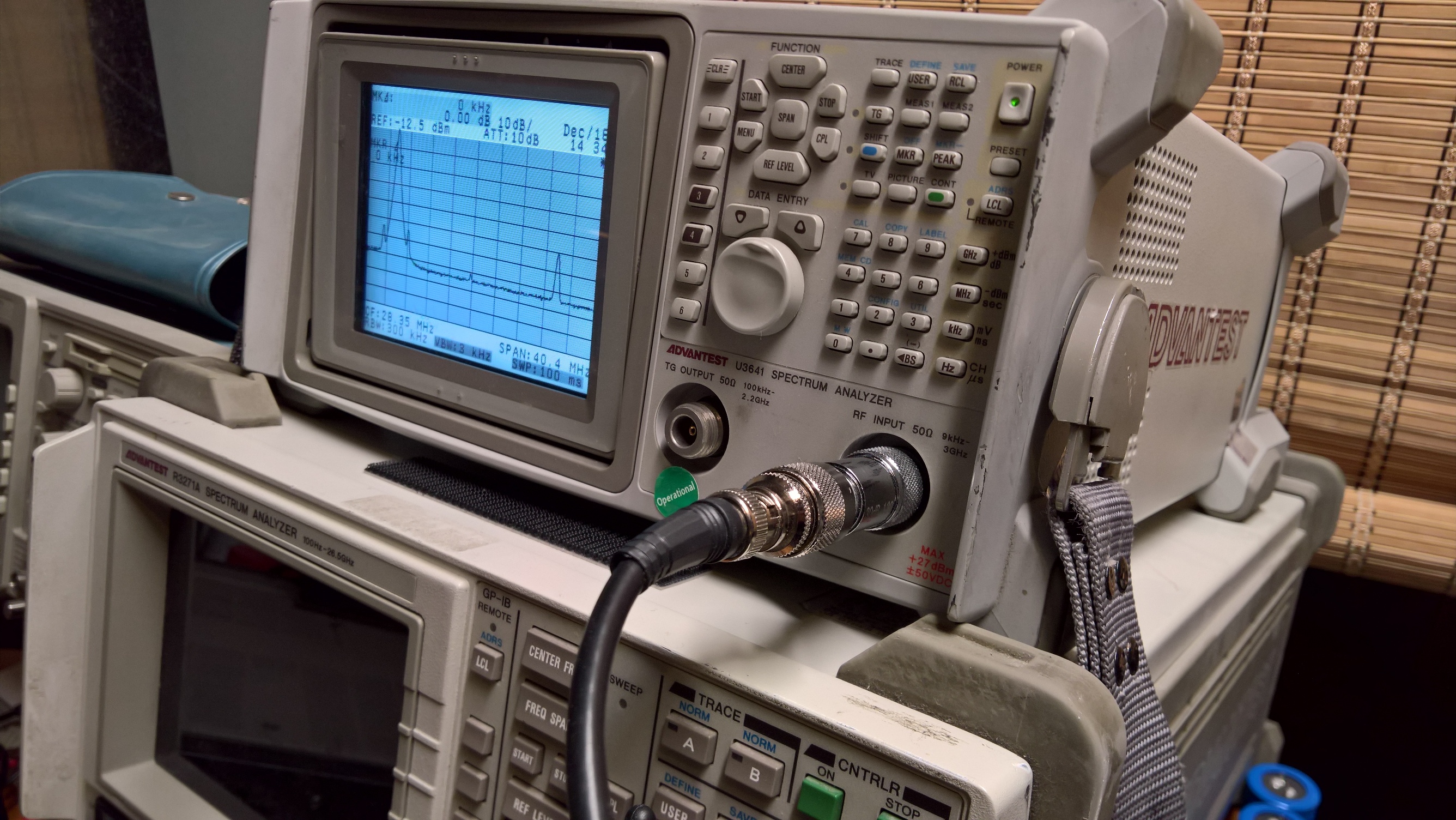
ADVANTEST R3271A SPECTRUM ANALYZER: Click HERE for pictures and complete info!
ADVANTEST R3271A SPECTRUM ANALYZER: Click HERE for pictures and complete info!
The more I used my FFT function, the more I yearned for an actual Spectrum Analyzer (SA). This was definitely a "want" and not a need. And the more I researched models and features, the more I succumbed to "salami theory". Why buy a SA with a range of 9KHz to 1.5 GHz for $600 when for just $100-$200 MORE I can have one that goes to 13.5 GHz. No, wait! For another $150 I can get one that goes from 100 Hz to 26.5 GHz! Or for a mere $2,500 more I could get one that goes from 30 Hz to 26.5 GHz (HP8563A with all the right options). You get the idea. I had to draw a line somewhere so I drew it at $800-$1,000. Fortunately, I found a super deal from a company called SES Sales (travist_tech on eBay) so I ended up spending less than $600. Check out the pix on the TEST EQUIPMENT page.
This will be a very useful tool for analyzing the output from the various TS-930S Power Amp options. I just need to read the instructions - all 600+ pages of them. It has a handle, but that's just to prop it up. This thing weighs as much as two concrete blocks.
USING A TEK TDS SERIES SCOPE WITH FFT AS A SPECTRUM ANALYZER: CLICK HERE FOR MORE COMPLETE INFO!
One advantage to a using a scope with FFT is that you can simultaneously display the waveform and the spectral display (FFT), plus the input signal level permitted by a scope is generally much higher than that of a Spectrum Analyzer (SA). Of course FFT is crude compared to a dedicated SA, and the SA is much more precise, but if you can't afford both instruments go for something like the Tektronix TDS 360. They can be found on eBay for $150 or so. Whatever you get, pick something with a high bandwidth and a fast sampling rate.
SIGNAL UNIT SWAP: IT WORKS!
I was itching to try this. BOTH of my 930S rigs are the "old" style, with the AM carrier control (VR22) on the underside of the board. With the later models, the carrier control adjusts the AM carrier level. Looking at the two schematics, I could see significant differences between the two boards, not just in the AM area but others as well. So I was aware that I might encounter some issues or areas where some functionality might be compromised. In fact, I might blow something up! But if the important features, such as CW, SSB, and FSK still worked, swapping out the board might be a good way to go if your board is bad and you can't fix it.
The big question was, would the new board work with the existing PLL system or would it need a partial or complete alignment per the Kenwood Service Manual? If the answer was "yes", then a swap might not be the way to go for some HAMs. For one thing, unless an OP knows positively that the replacement board worked correctly beforehand, many hours might be wasted trying to make the defective replacement board work.
NEW INFO: I tried TWO late model boards in my older "test bed" radio. BOTH work perfectly, and I'm using one of them now. The band switching system, CW, SSB, and FSK work just as though the replacement board was the original. This is in contrast to the first replacement I performed, where I replaced a bad late model board with a similar board. THAT one worked, but I had to perform an alignment to get the band switching to work properly (steps 1-7, PLL, Service manual). Without any mods, the only thing that won't work will be AM. The mod involves simply installing a diode in the switch board that is already there in the newer radios. The older model relied on VR22. Without the diode, there will be no carrier so what comes out will sound just like SSB.
I've worked a lot of contacts with the radio with the newer board. My scope output looks perfect, and I get great audio reports.
THE COMPUDIGITAL (K6IOK) POWER SUPPLY KIT- IT'S THE EASY WAY TO FIX YOUR POWER SUPPLY!
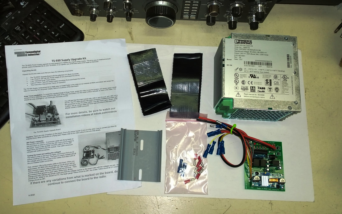
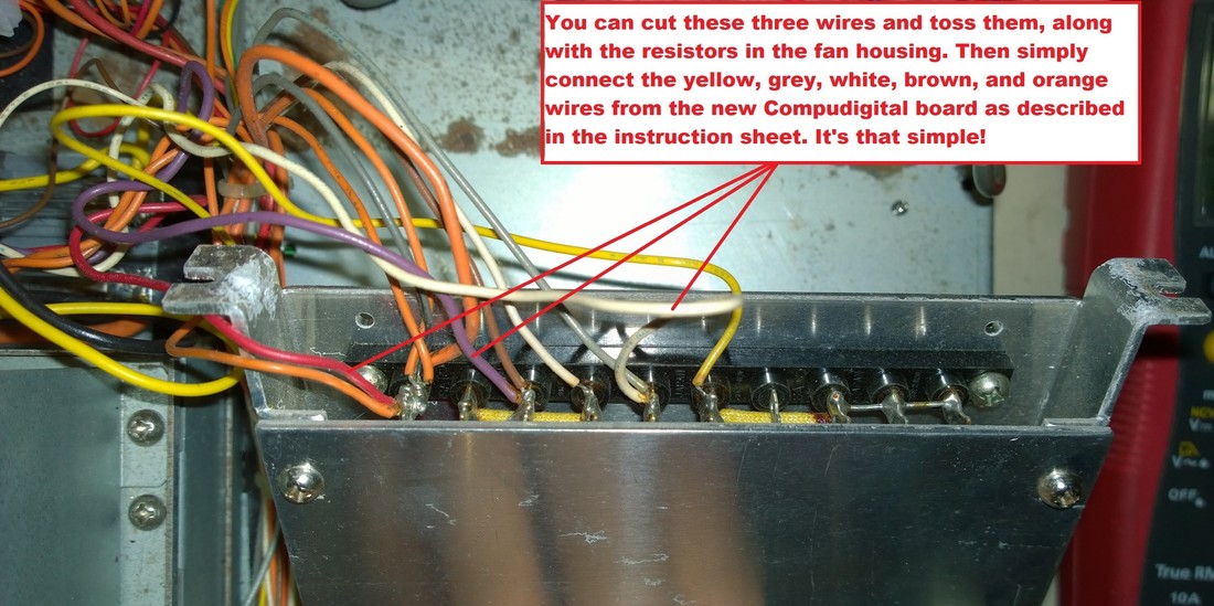
If you need to rebuild your Kenwood TS-930S power supply, but you don't want want to modify your old AVR board, you can buy a ready made kit from Jeff Hilliard of Compudigital that will simplify the process for you.
Seriously, it's so simple even a CAVEMAN could do it! (Sorry, GEICO) Click HERE for my write-up.
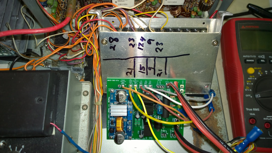
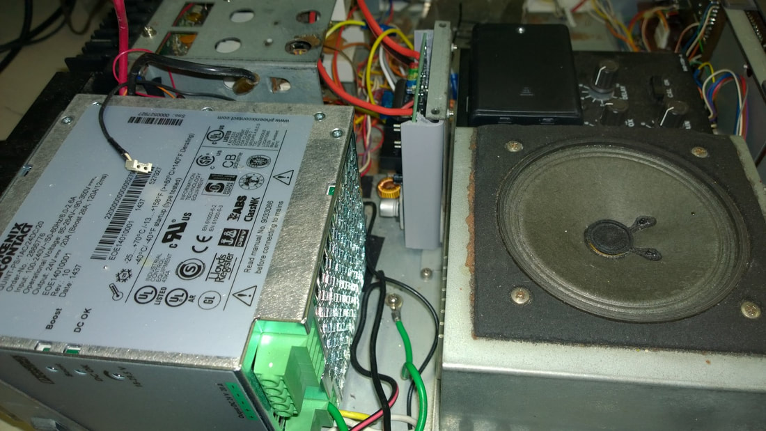
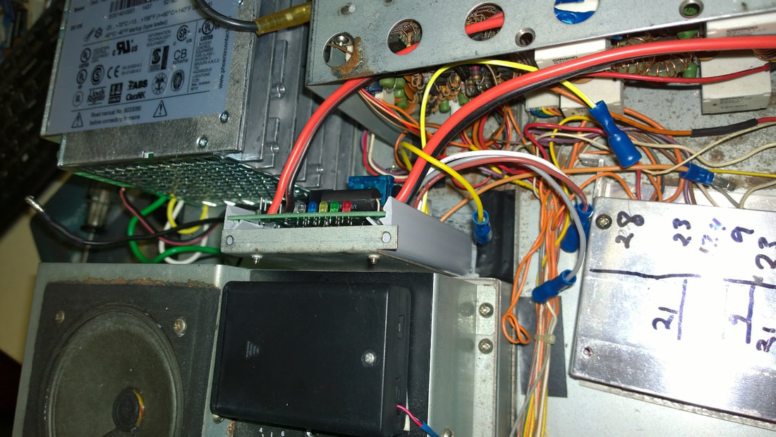
The kit has a replacement AVR board that eliminates the need for the various sub-voltage regulators, resistors, Zener diodes, and even the 5-watt PA current sense resistor. For a very fair price you get a BRAND NEW 20/26-amp Phoenix Contact Quint, the AVR/power board, and electrical and mounting hardware. The board contains circuitry to provide all the necessary voltages, reduced-voltage fan outputs, and the Ic and Vc voltages for the IcA and IcB ("sense") circuit. Trust me, it's worth it.
My installation was slightly different than most because both of my 930s rigs have the old low-serial numbers. I installed the kit in my rusty but trusty Test Bed radio. JEFF is about to release a new version of his board (Ver. 3) and I plan to install that model in my everyday 930S. The new board will have an improved connector system.
The pictures below tell the story, or you can download my write-up from the above link. Click on each picture below to get a huge version. I didn't mount the Quint or the new AVR replacement the way Jeff shows in his videos and instructions. But my way works well for me.
Seriously, it's so simple even a CAVEMAN could do it! (Sorry, GEICO) Click HERE for my write-up.
The kit has a replacement AVR board that eliminates the need for the various sub-voltage regulators, resistors, Zener diodes, and even the 5-watt PA current sense resistor. For a very fair price you get a BRAND NEW 20/26-amp Phoenix Contact Quint, the AVR/power board, and electrical and mounting hardware. The board contains circuitry to provide all the necessary voltages, reduced-voltage fan outputs, and the Ic and Vc voltages for the IcA and IcB ("sense") circuit. Trust me, it's worth it.
My installation was slightly different than most because both of my 930s rigs have the old low-serial numbers. I installed the kit in my rusty but trusty Test Bed radio. JEFF is about to release a new version of his board (Ver. 3) and I plan to install that model in my everyday 930S. The new board will have an improved connector system.
The pictures below tell the story, or you can download my write-up from the above link. Click on each picture below to get a huge version. I didn't mount the Quint or the new AVR replacement the way Jeff shows in his videos and instructions. But my way works well for me.
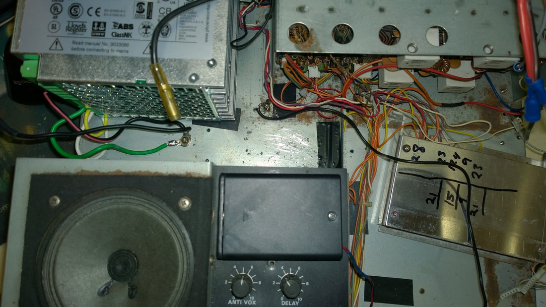

NOTE: My 930s runs ALL DAY, and it remains STONE COLD. No heat whatsoever. As in zero! Right now I'm working on an engineering project and I have Plans and other papers on top of my radio. Again, no heat!
KENWOOD COMPENDIUM INFO
The first section of the Compendium of Repair describes how to replace your original Kenwood TS-930S power supply with a 24 to 29.5 volt (adjustable) Phoenix Quint commercial-grade switching power supply. There are several models that will fit and work perfectly in the radio, including one that delivers 20-amps nominal, with up to 26 amps in "Boost Mode", which translates to 624 watts. At a voltage setting of 28-28.5 volts, that translates into approximately 22 amps. Data from Phoenix Contacts indicates that the voltage vs. current relationship is linear.
Dave Phillips, KB7JS, pioneered the 20/26-Amp conversion. It really performs. I converted both of my 930'S to that model, and I've added my info to a button below and to the Compendium. I've also posted some photos and information on my project at the bottom of this page. That Quint is my "go to" model now.
SPARE PARTS: I would like to extend my sincere thanks to those of you who have donated parts for my experiments. Dave Phillips (KB7JS) has donated two PA's and a Signal Unit (plus several metric tonnes of technical information) and contributor Luis Velazquez (K4BTA) sent me a complete 930S to rebuild and experiment with so I wouldn't have to keep tearing my main 930S apart. And Jeff Hilliard of Compudigital donated a complete 930S conversion kit for testing and review. These donations of time, technical knowledge, and equipment truly exemplify the "Ham Spirit".
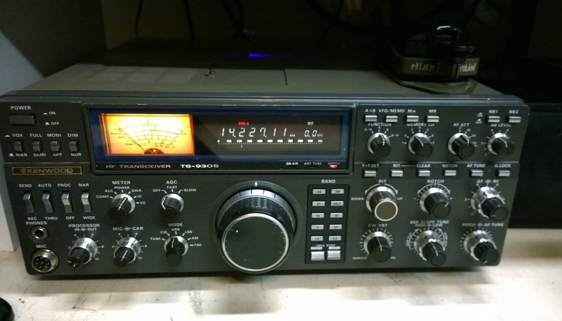
The radio that Luis donated received well but it needed a Quint PS which I already had. I installed a longer RF input cable and extended the TXC wires so now I have a "test bed" TS-930S rig to experiment with. You can see it in the foreground in the picture at the top of the page. With the longer cables I can run it with the various PA's lying out flat behind it, making it easy to measure voltages, check scope patterns, and so forth. Luis included a PA that he rebuilt using 2sc1307's, yet another viable choice for drivers. It had a strange output power problem that turned out to be an intermittent MRF422 final output "pill". I replaced both pills with spares that he included, changed the feedback resistors, and it works great now. Luis had already reduced the voltage to the 1307's using a 12-volt regulator to control the gain, but the increased negative feedback really helped to tame the 215 gain of those 1307's. The increased feedback idea was developed by Merit Arnold (W6NQ). I worked about a hundred contacts during the last two contests with that PA and it's very stable. That solution is now PA rebuild Option 4, below.
Dave Phillips, KB7JS, pioneered the 20/26-Amp conversion. It really performs. I converted both of my 930'S to that model, and I've added my info to a button below and to the Compendium. I've also posted some photos and information on my project at the bottom of this page. That Quint is my "go to" model now.
SPARE PARTS: I would like to extend my sincere thanks to those of you who have donated parts for my experiments. Dave Phillips (KB7JS) has donated two PA's and a Signal Unit (plus several metric tonnes of technical information) and contributor Luis Velazquez (K4BTA) sent me a complete 930S to rebuild and experiment with so I wouldn't have to keep tearing my main 930S apart. And Jeff Hilliard of Compudigital donated a complete 930S conversion kit for testing and review. These donations of time, technical knowledge, and equipment truly exemplify the "Ham Spirit".
The radio that Luis donated received well but it needed a Quint PS which I already had. I installed a longer RF input cable and extended the TXC wires so now I have a "test bed" TS-930S rig to experiment with. You can see it in the foreground in the picture at the top of the page. With the longer cables I can run it with the various PA's lying out flat behind it, making it easy to measure voltages, check scope patterns, and so forth. Luis included a PA that he rebuilt using 2sc1307's, yet another viable choice for drivers. It had a strange output power problem that turned out to be an intermittent MRF422 final output "pill". I replaced both pills with spares that he included, changed the feedback resistors, and it works great now. Luis had already reduced the voltage to the 1307's using a 12-volt regulator to control the gain, but the increased negative feedback really helped to tame the 215 gain of those 1307's. The increased feedback idea was developed by Merit Arnold (W6NQ). I worked about a hundred contacts during the last two contests with that PA and it's very stable. That solution is now PA rebuild Option 4, below.
TEST BED
I recently worked on a TS-940S PA. The board is identical to that in the 930S. In fact, the board part # is the same. But the connections are a bit different. I worked quite a few stations in a contest recently with the setup below, including France and North Macedonia.

KENWOOD POWER AMP INFORMATION
No supplier, even Eleflow, has "low-gain" drivers for the 930S PA anymore. But that's not really a problem. There are lots of ways to make the newer MRF485's from Eleflow work. Note that I said "from Eleflow". There are a lot of 485's floating around on auction sites that are fakes. Some even have plastic collector tabs. These are total junk. Avoid them like the plague.
I now have four PA's with successful solutions, including the use of 2SC1969's as drivers which are described in the PDF below. Option 4, using 2SC1969 drivers is beginning to emerge as the "go to" solution, because it appears that there are several sources for quality 1969's with reasonable prices and hFe levels. RF Parts is one of those suppliers. As before, stay away from auction site stuff unless it's from a reputable place like RF Parts, Dalbani, etc. If you can find quality MRF 485's with a gain of 70-80, Option 3 works well. Both of my 930S rigs use Option 3 PA's.
I need to make some additions and changes to the Compendium, so there will be a Revision 9. Part of the reason is that I recently repaired a TS-930S for someone. The original plan was to use my own Compendium as a guide to make sure there are no errors or omissions. Unfortunately, his problem was caused by issues with the Signal Unit. But that repair effort prompted me to add a couple sections to the Compendium to cover some of the other issues HAMS might encounter when trying to repair their own rigs, and for that matter, to help them decide whether or not they wish to proceed with the repair effort. As an aid, I've added a button below that describes some of the issues that confronted me when I repaired that radio.
ADDING A PANADAPTER-LIKE DISPLAY TO YOUR TS-930S.
Click HERE for a write up by Contributor Ed Corse.
DOWNLOADS: COMPENDIUM OF REPAIR FILES
SIGNAL UNIT FILES (UNDER CONSTRUCTION)
Since I'm behind schedule getting the updated Compendium together, I might as well put some useful information on the site so that owners who suspect that their low or no output problem might be related to their Signal Board. Here are some buttons that link to some future sections of the new Compendium. I also decided to add some of the other sections relating to the VFO, tilt-down front panel, and more.
CONTRIBUTORS' PAGES
HOW OTHERS FIXED THEIR KENWOOD TS-930S RADIOS: The buttons below will open up Acrobat documents that show how others have installed their power supplies or repaired their radios.
OTHER KENWOOD FILES AND SCHEMATICS
SWAN RADIO INFORMATION
using a swan 117xc power supply to power a collins kwm-2
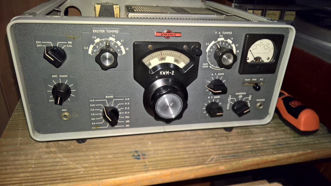
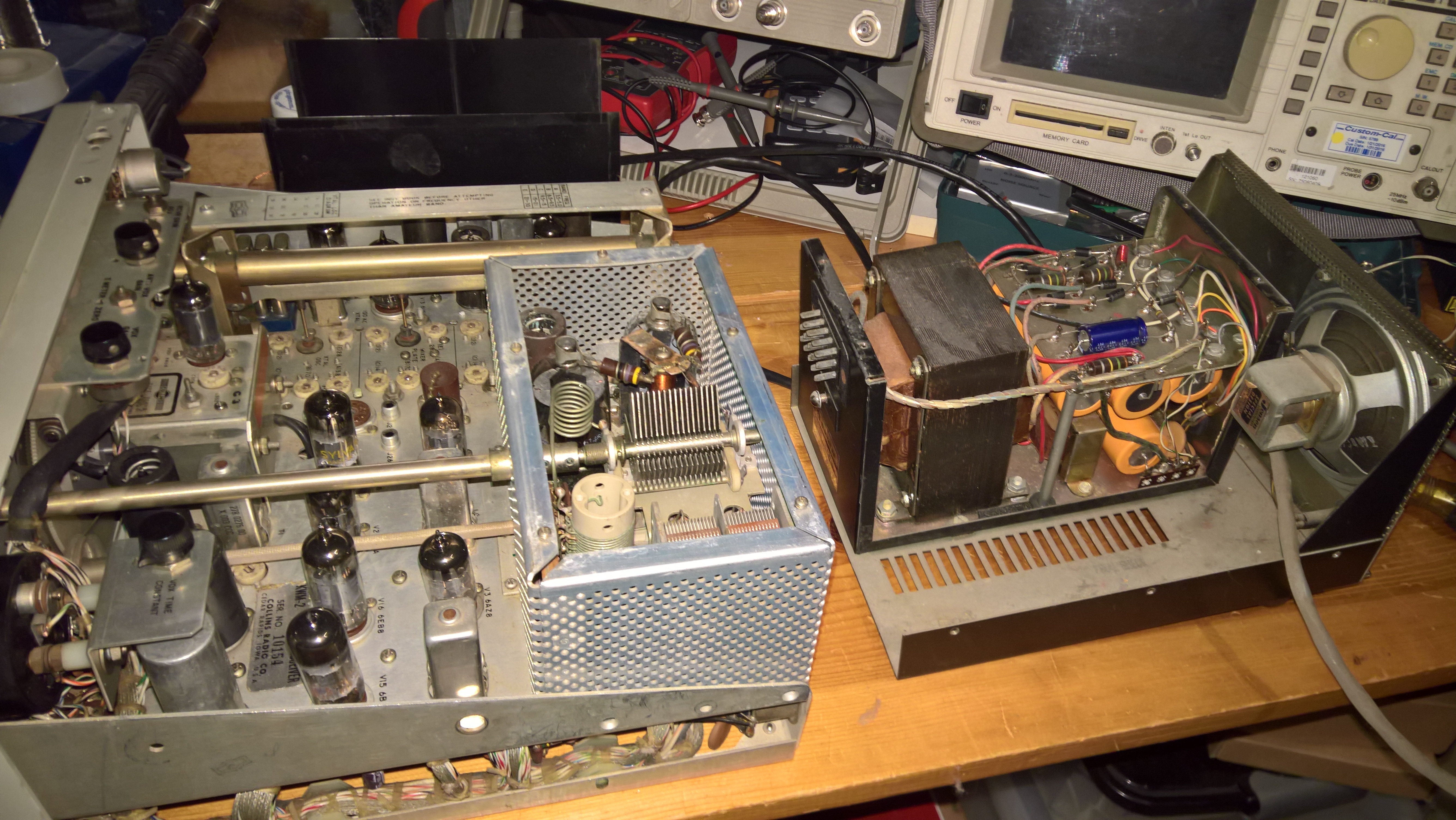
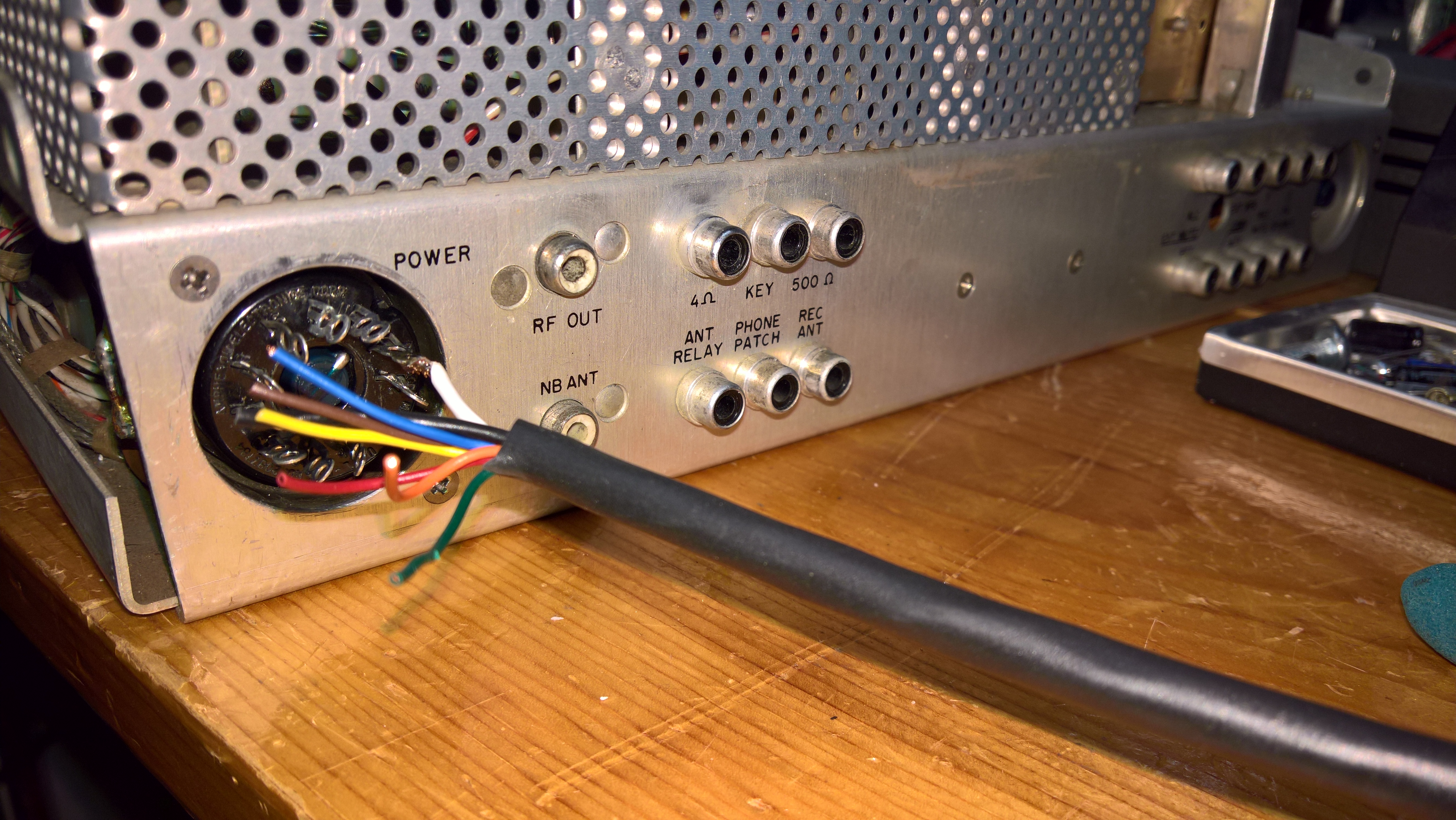
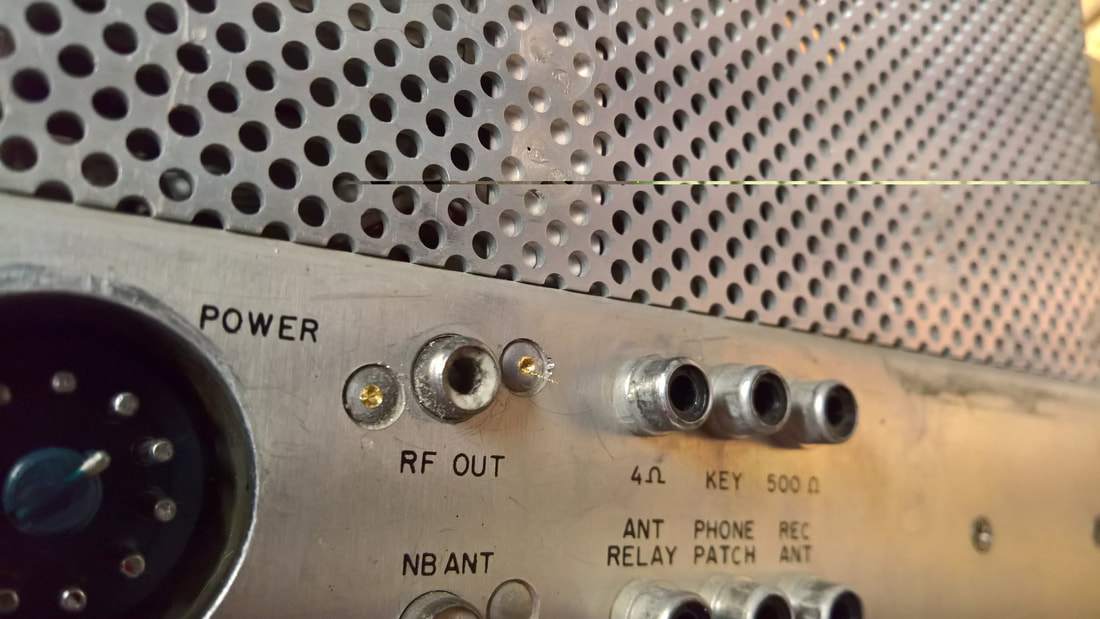
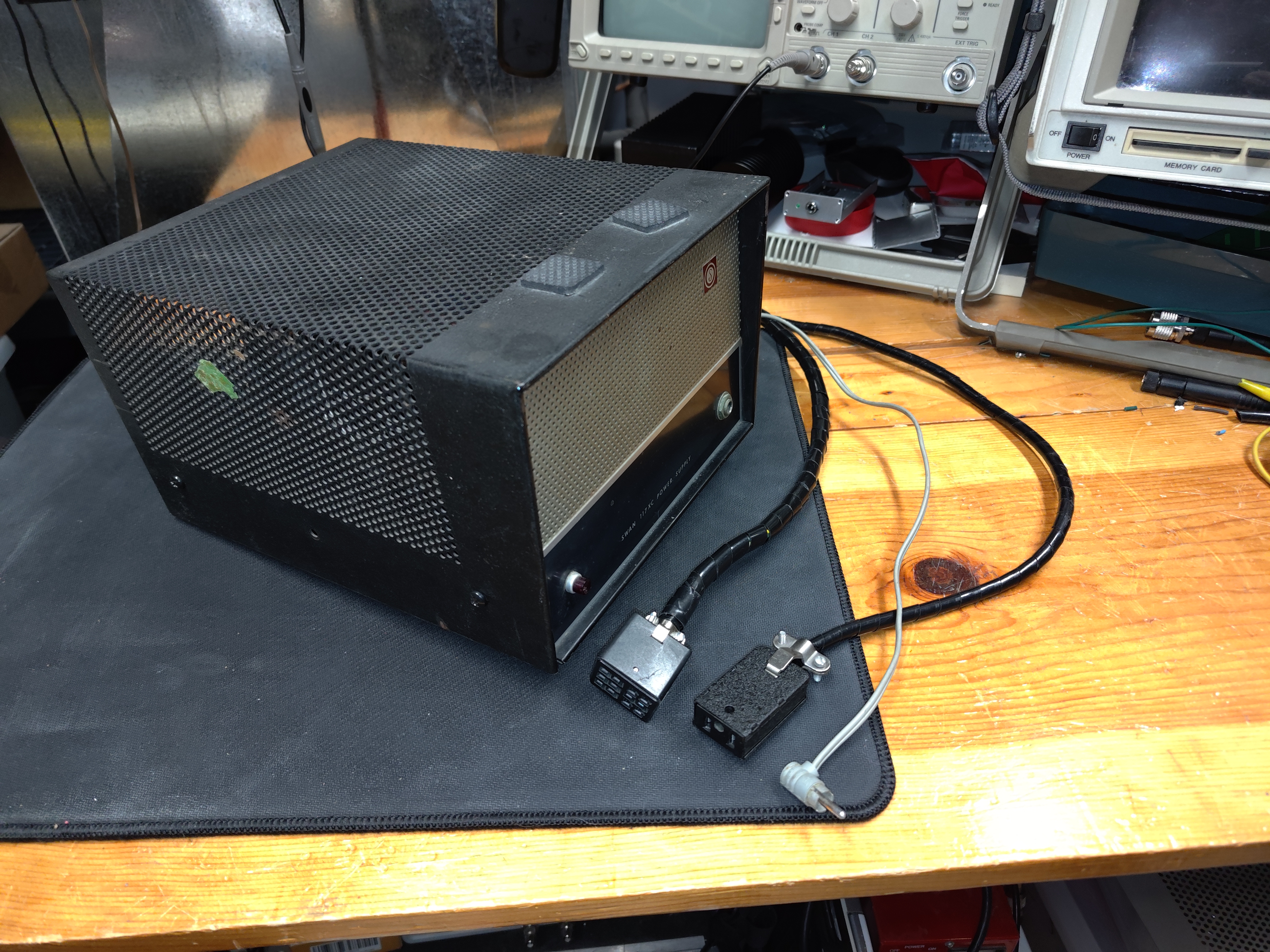
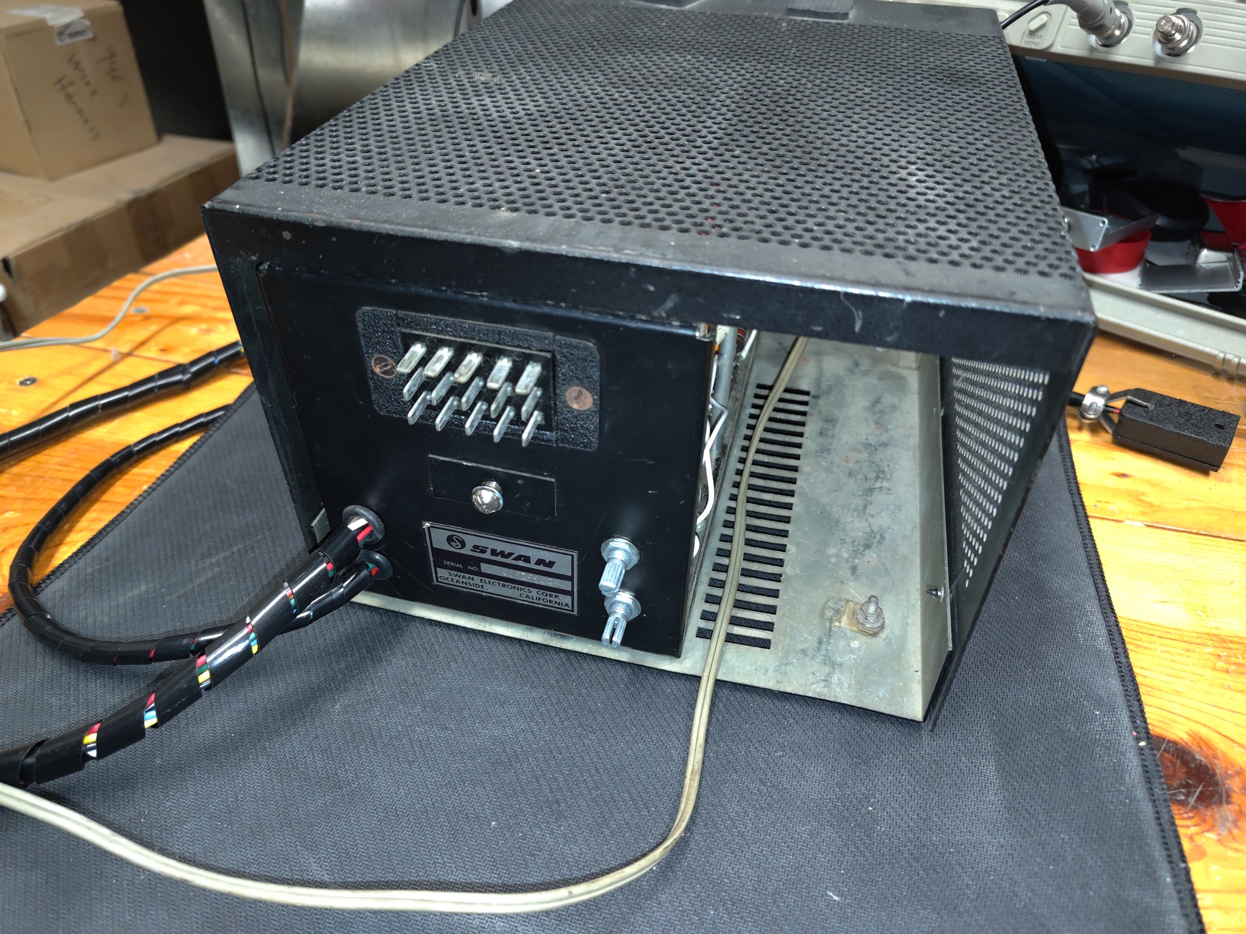
I broke down and bought what I thought was a clean Collins KWM-2 on eBay. I've always wanted to try Collins. But the Collins 516F-2 power supply sells for a king's ransom, so I decided to build an adapter cable so that the Collins can be powered by the Swan 117XC Power Supply. The SWAN power supply has plenty of power, and the 117XC's -100 volt grid bias can be used for the Collins -55 to -80 volt bias using a potentiometer. Both radios use 275 and 800 volts for the low and high voltages, and the Collins plug can be wired for 12.6 volt filaments (AC or DC).
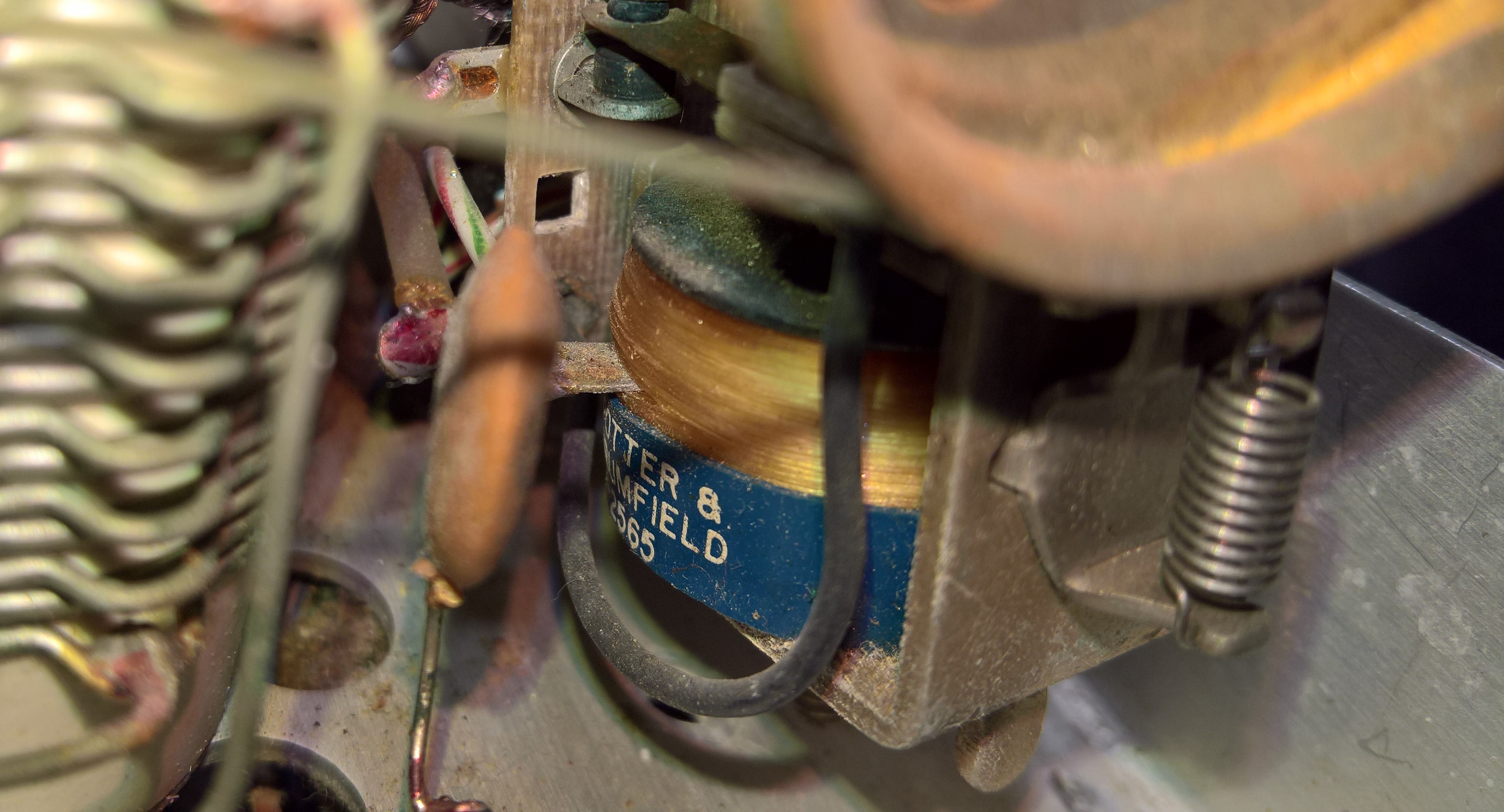
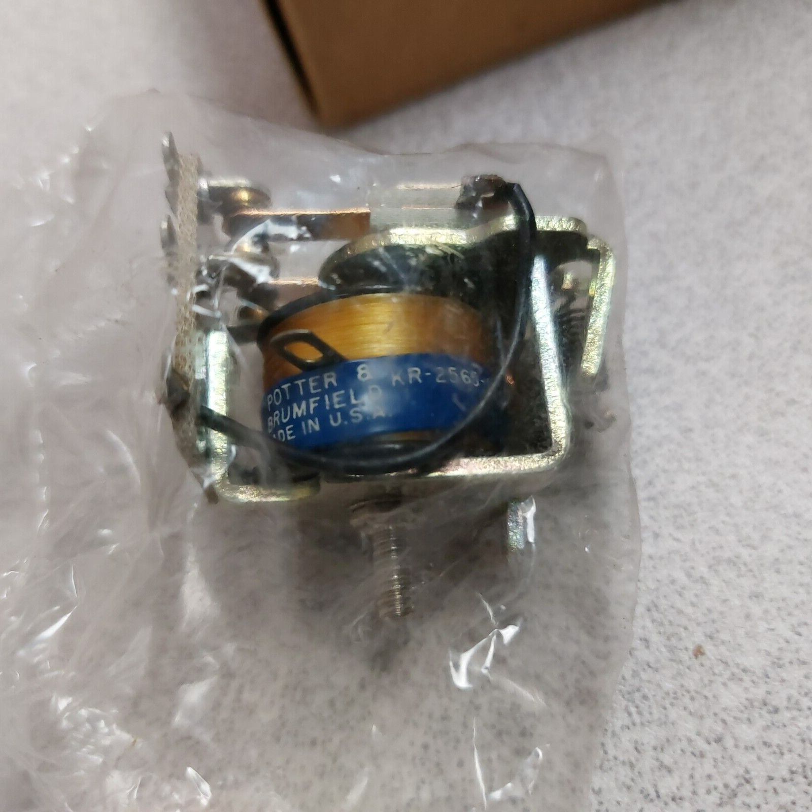
The KWM-2 wasn't quite a clean as the seller represented. I found more than 25 aftermarket replacement parts, including a couple Chinese MIEC electrolytic caps, and some values of the replacement resistors were wrong. The tuning dial was a train wreck. The antenna relay was corroded and the RF OUT RCA jack was a mess, as was the cable to the PA. But it did work well on 40M - well, except that I had to use a frequency counter to tune the rig. I replaced the RF output connector with an SO-239, and the transmit relay, which was rusted and pitted. THAT fixed the intermittent transmit and receive, but as I was tuning up on 80M I saw a spark and the output dropped to 5 watts. After some sleuthing, I discovered that the 1K resistor that provides 275VDC to the plate of the 6CL6 driver had a hairline crack. I replaced it but then while trying to align/fix the other bands, smoke rolled out of the section near T2. THAT turned out to be an incorrect resistor value in one of the "new" blue metal film 1/2 watt resistors. It was supposed to be 1K ohms, but instead it was 220 ohms. It was adjacent to a 220 uH RF choke on the schematic and I think someone got confused. I DECIDED TO SELL IT! I FOUND A HURRICANE!
The KWM-2 wasn't quite a clean as the seller represented. I found more than 25 aftermarket replacement parts, including a couple Chinese MIEC electrolytic caps, and some values of the replacement resistors were wrong. The tuning dial was a train wreck. The antenna relay was corroded and the RF OUT RCA jack was a mess, as was the cable to the PA. But it did work well on 40M - well, except that I had to use a frequency counter to tune the rig. I replaced the RF output connector with an SO-239, and the transmit relay, which was rusted and pitted. THAT fixed the intermittent transmit and receive, but as I was tuning up on 80M I saw a spark and the output dropped to 5 watts. After some sleuthing, I discovered that the 1K resistor that provides 275VDC to the plate of the 6CL6 driver had a hairline crack. I replaced it but then while trying to align/fix the other bands, smoke rolled out of the section near T2. THAT turned out to be an incorrect resistor value in one of the "new" blue metal film 1/2 watt resistors. It was supposed to be 1K ohms, but instead it was 220 ohms. It was adjacent to a 220 uH RF choke on the schematic and I think someone got confused. I DECIDED TO SELL IT! I FOUND A HURRICANE!


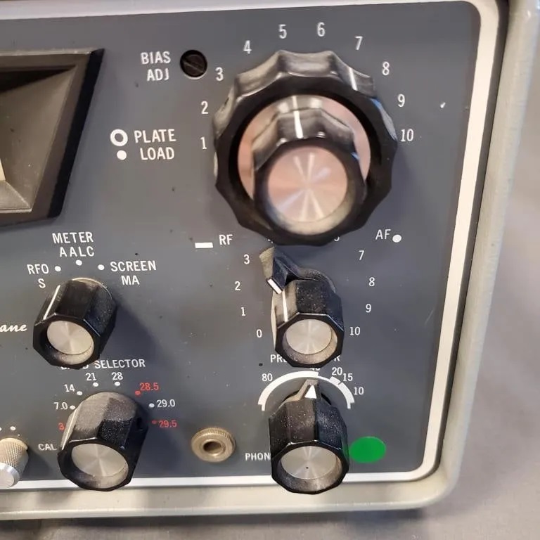
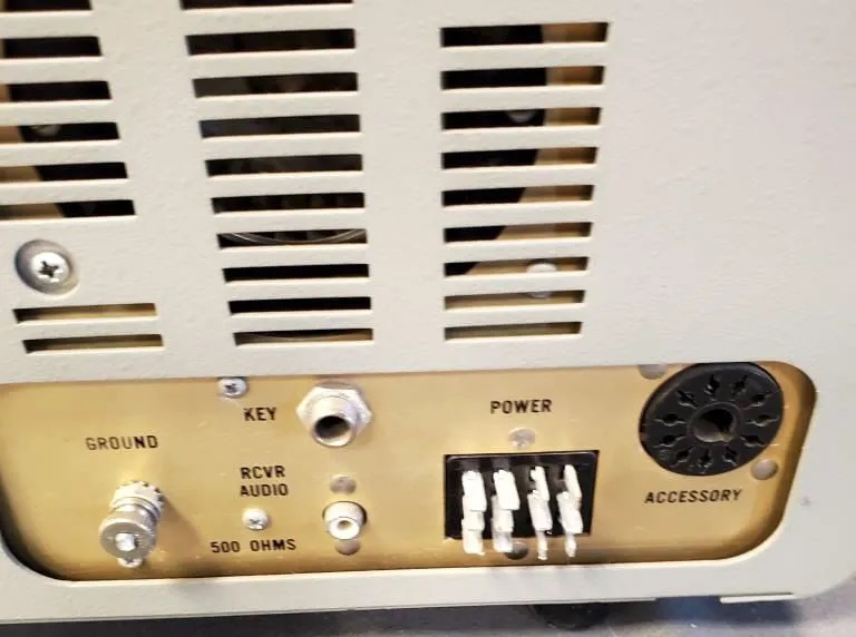
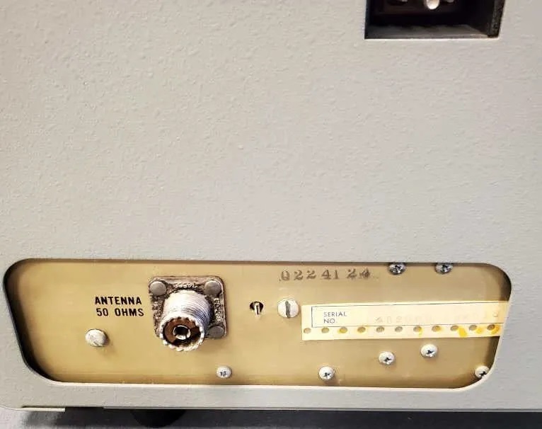
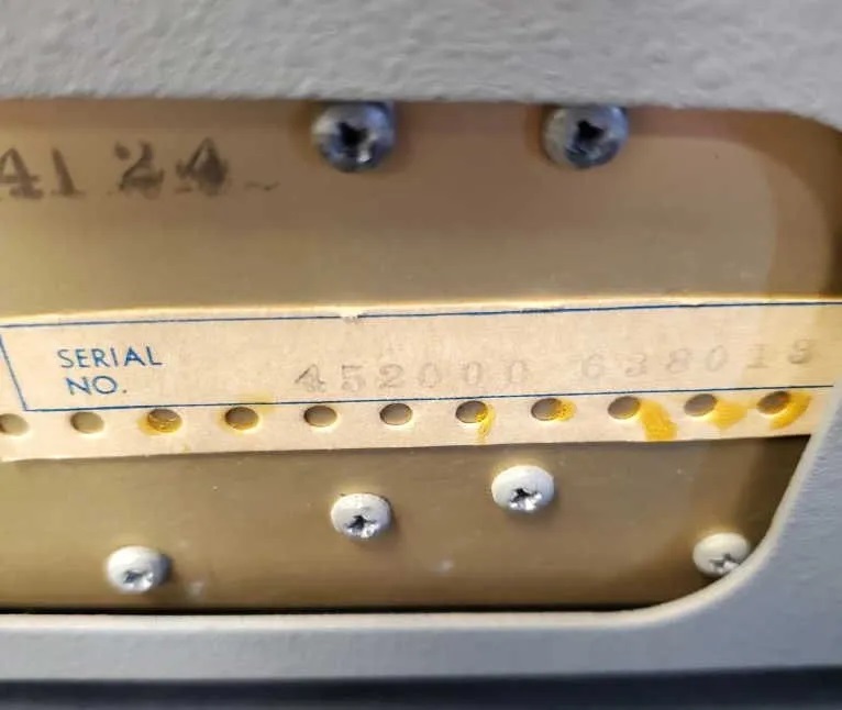
HALLICRAFTERS HURRICANE!
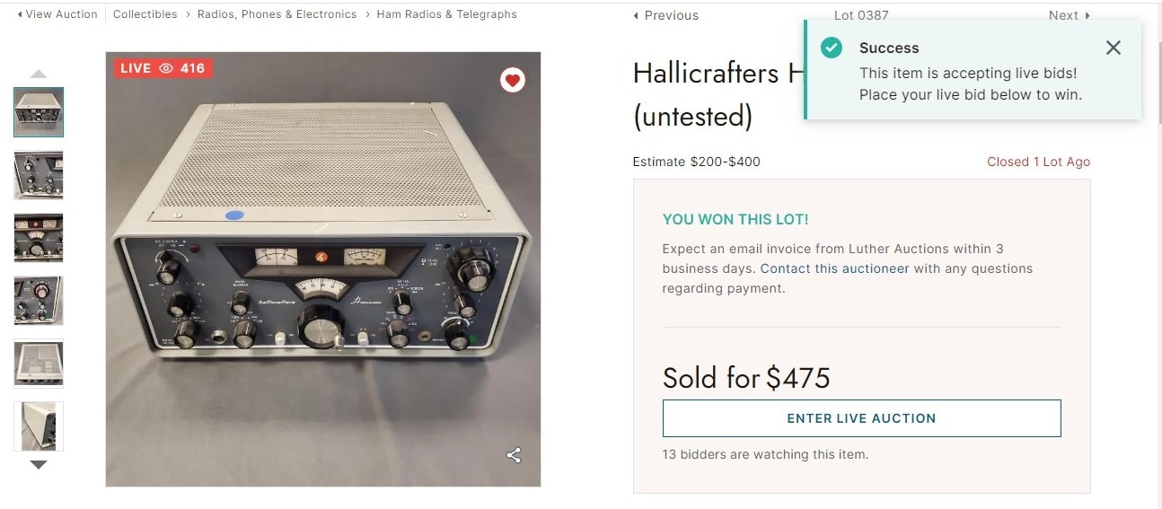
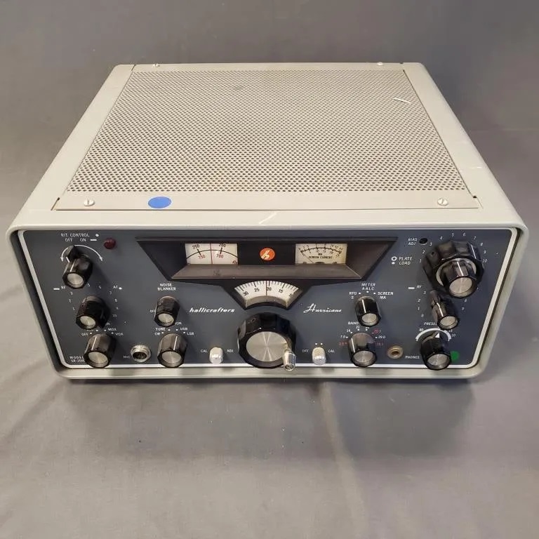
I was browsing some HIBID auctions, and I came across a beautiful-looking Hallicrafters Hurricane that appeared to be unmolested, so I bid on it.
I was winning at $100 until the end, but last-second bidders drove the price up into the $500 range. There was no power supply but I'm powering the receiver section as I write this with one of my Swan 117XC power supplies. UPDATE: I managed to get the transmit mode operational today using the 800-volt tap in the 117XC. Here is the auction ad and its pictures.
I was winning at $100 until the end, but last-second bidders drove the price up into the $500 range. There was no power supply but I'm powering the receiver section as I write this with one of my Swan 117XC power supplies. UPDATE: I managed to get the transmit mode operational today using the 800-volt tap in the 117XC. Here is the auction ad and its pictures.
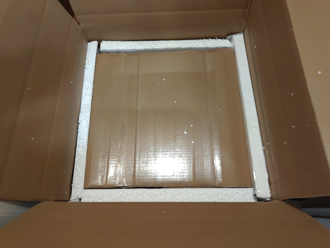
the radio arrives
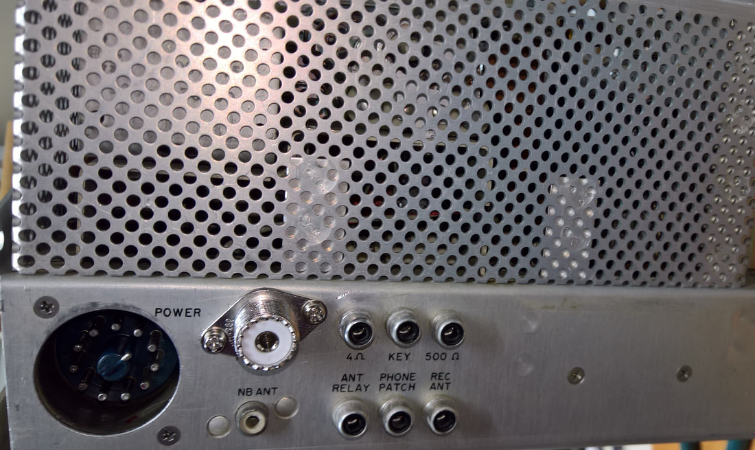
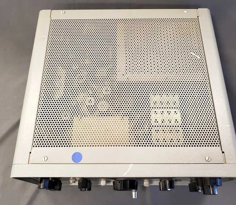
The radio arrived, and was unmolested. As I awaited the delivery, dark thoughts went through my mind. Would the 8122 tubes be in there? Would I find 20-30 cheap aftermarket parts like I found in the Collins, many of them simply tacked onto the leads from the old removed part? I won this for $475, but with the 25% "premium", and taxes and fees, I paid $583. Add in the $147 for shipping and the inflated priced double-boxes, and my total investment is $730. If the radio was adulterated, I would be out of luck since certain parts are super hard to find. It would go on eBay as "parts or not working" or I would part it out.
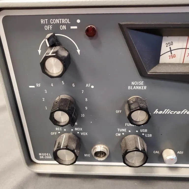
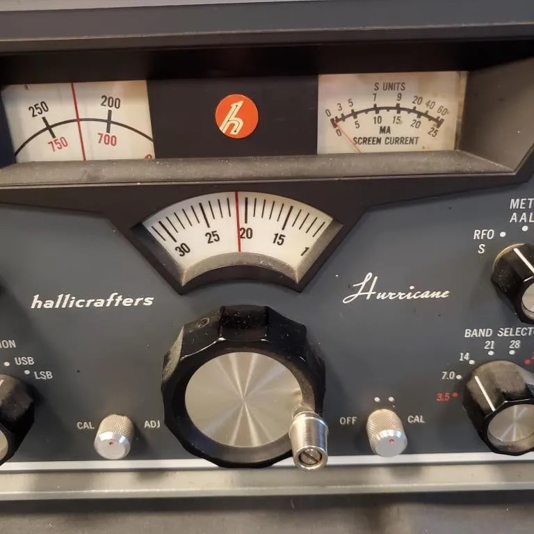
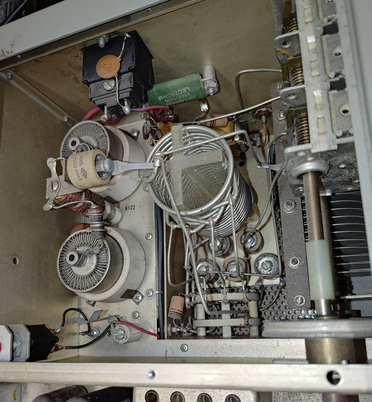
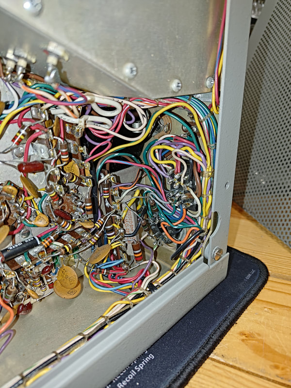
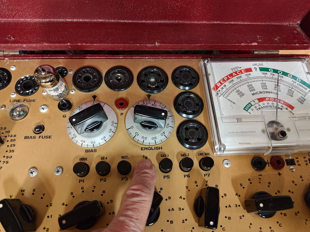
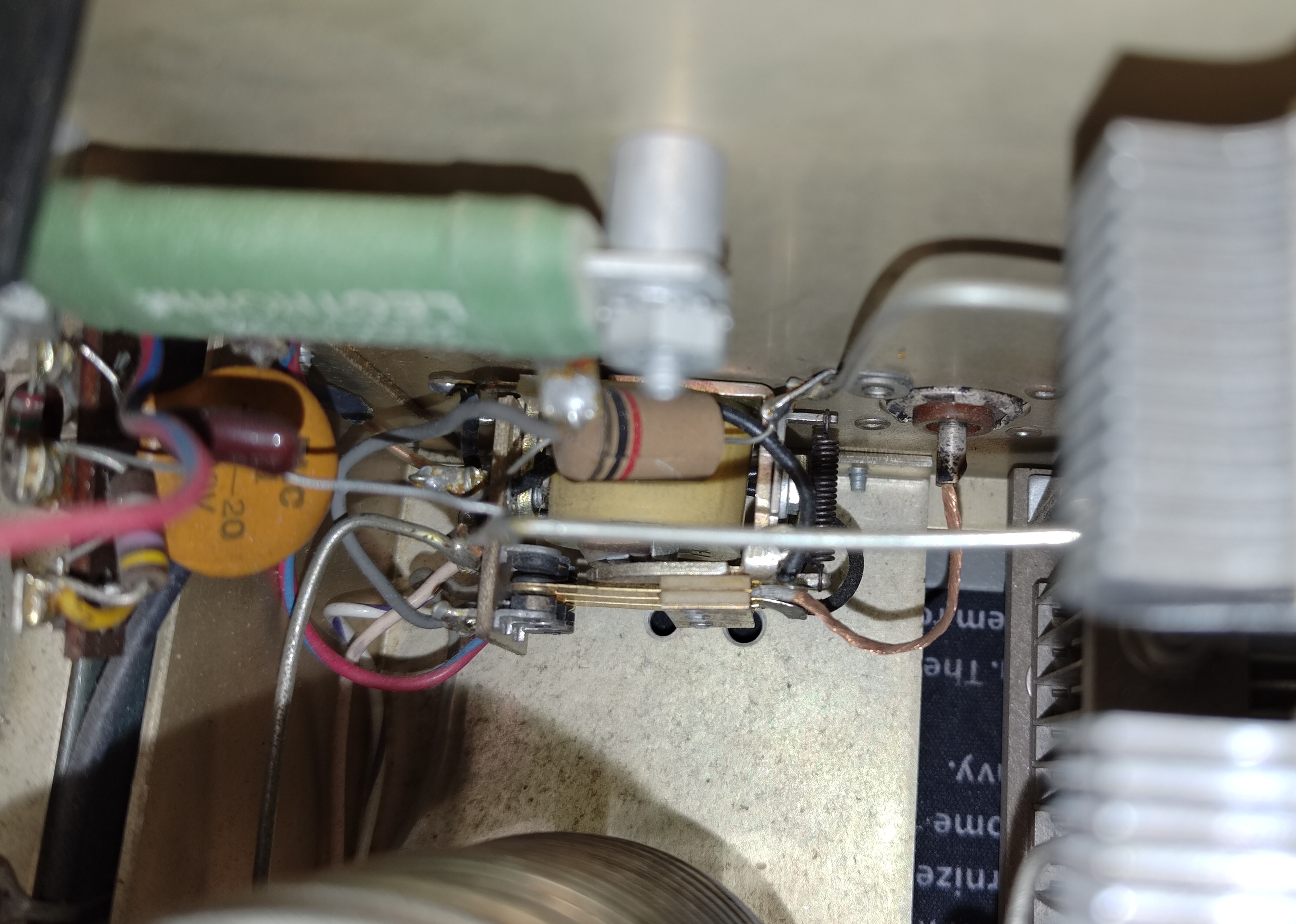
But the radio is completely original. No golden screwdriver stuff. I took the bottom cover off and all the OEM parts were there. All the knobs turn freely and nothing is bent. I gave it a light dusting and I've tested all the tubes except for the 8122's. They are all Hallicrafters branded tubes and they're all good. I can check the 8122 filaments with a DMM and check for shorts, but that's about it. I think.The radio is really pretty, with the exception of a large scratch on the top of the bezel that looks like it happened at the auction house. It's dead center so if I can't find Hallicrafters grey touch up paint I'll find a cool sticker to put over it for now. I might even have some 1" x 2" metallic stickers with my call sign made up. Here are some actual pictures.
But the radio is completely original. No golden screwdriver stuff. I took the bottom cover off and all the OEM parts were there. All the knobs turn freely and nothing is bent. I gave it a light dusting and I've tested all the tubes except for the 8122's. They are all Hallicrafters branded tubes and they're all good. I can check the 8122 filaments with a DMM and check for shorts, but that's about it. I think.The radio is really pretty, with the exception of a large scratch on the top of the bezel that looks like it happened at the auction house. It's dead center so if I can't find Hallicrafters grey touch up paint I'll find a cool sticker to put over it for now. I might even have some 1" x 2" metallic stickers with my call sign made up. Here are some actual pictures.
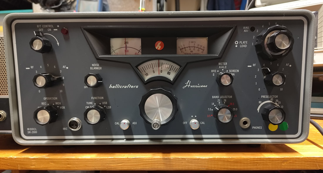
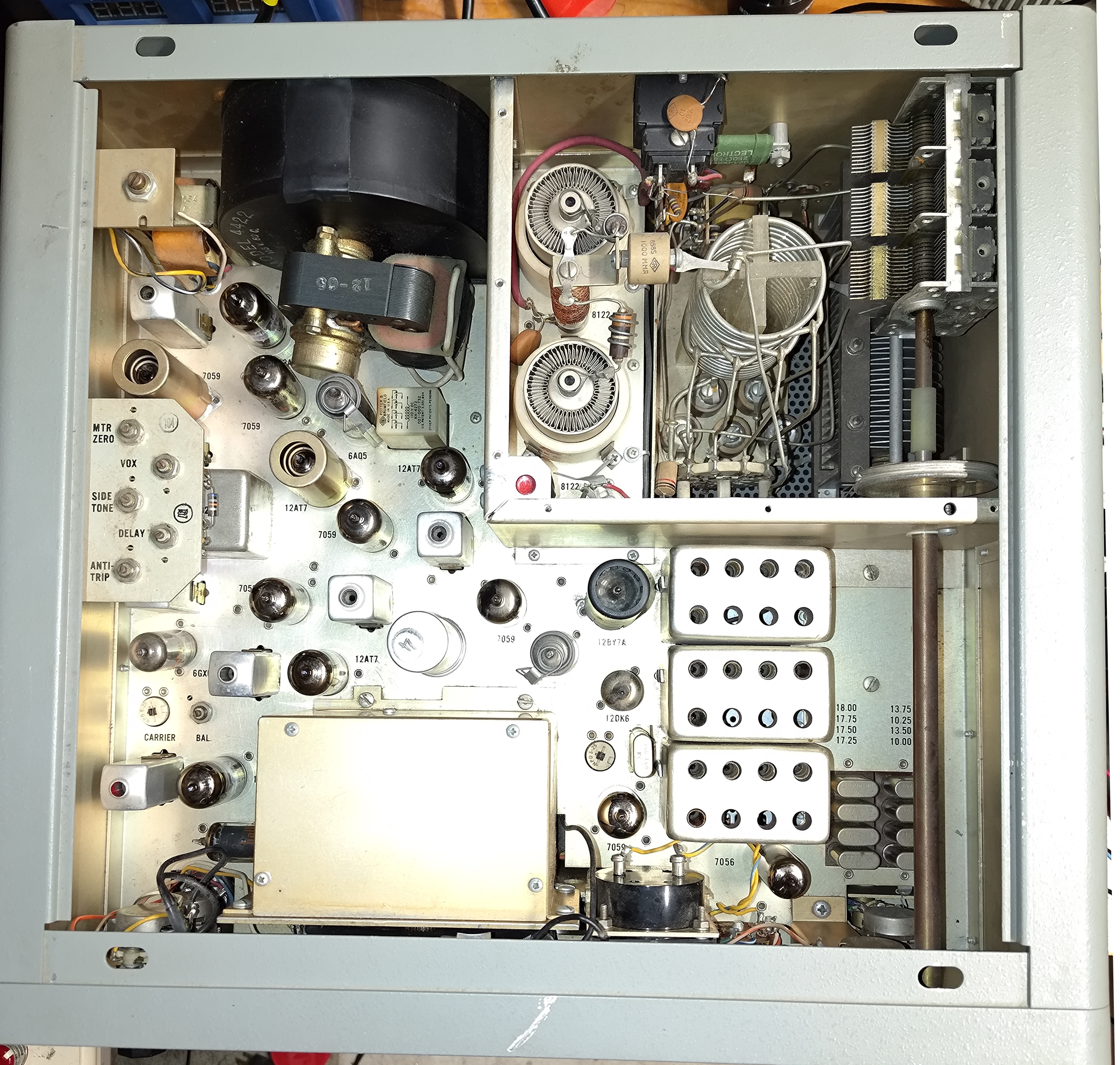
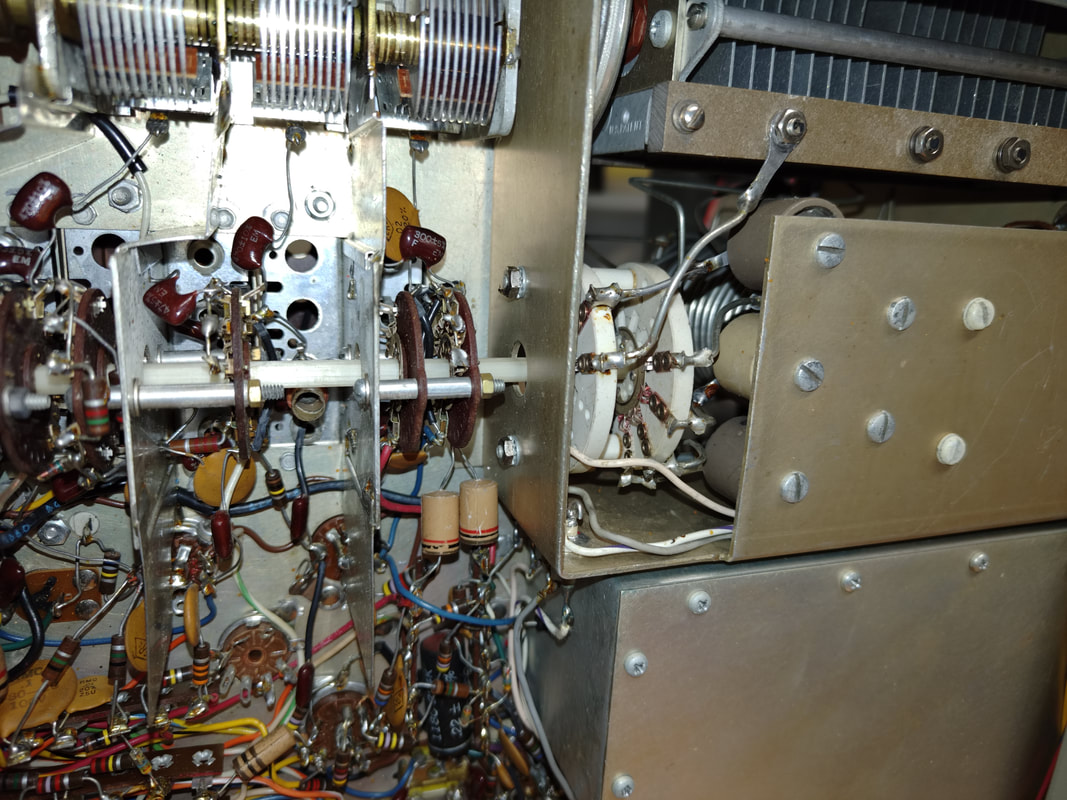
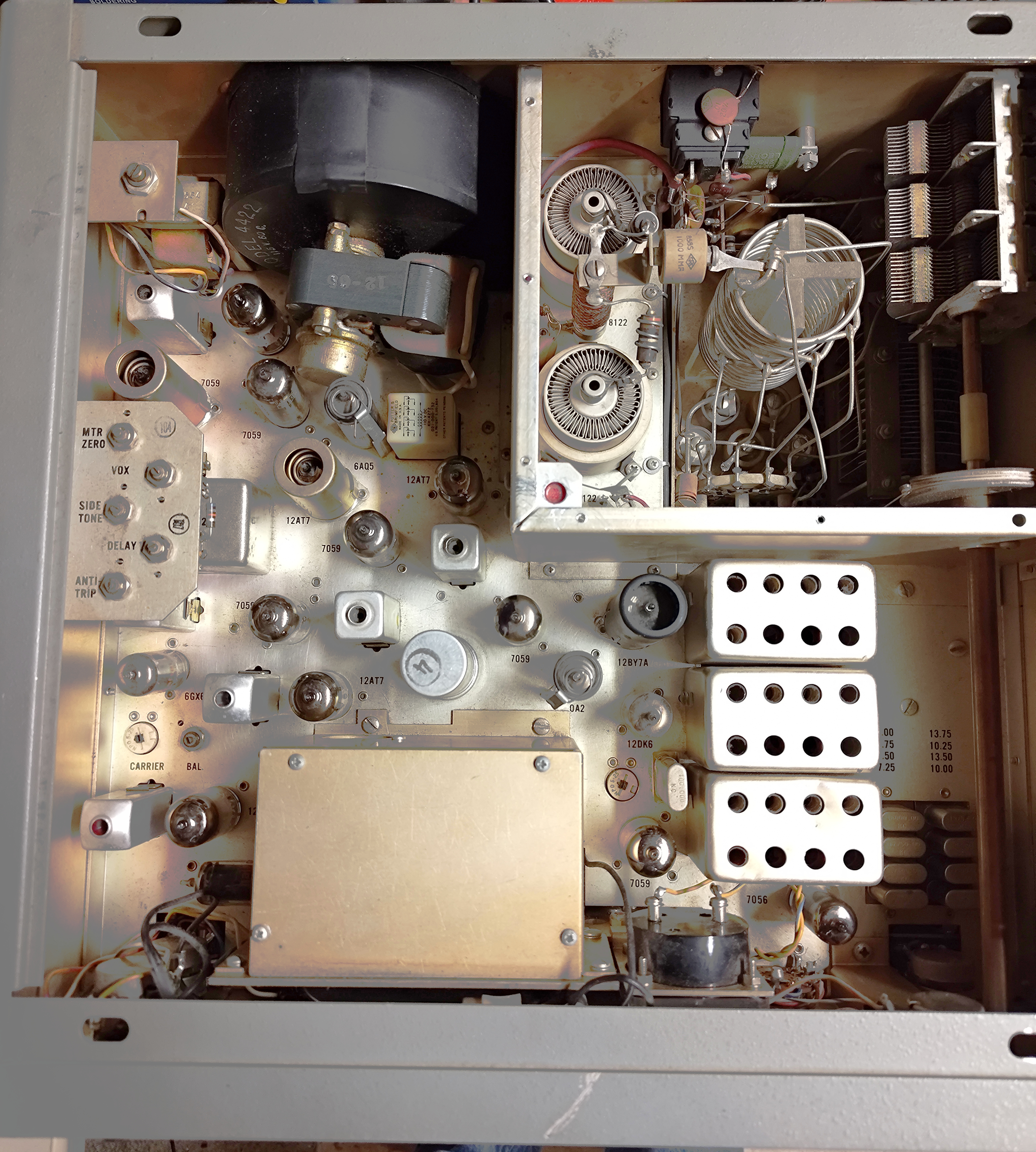
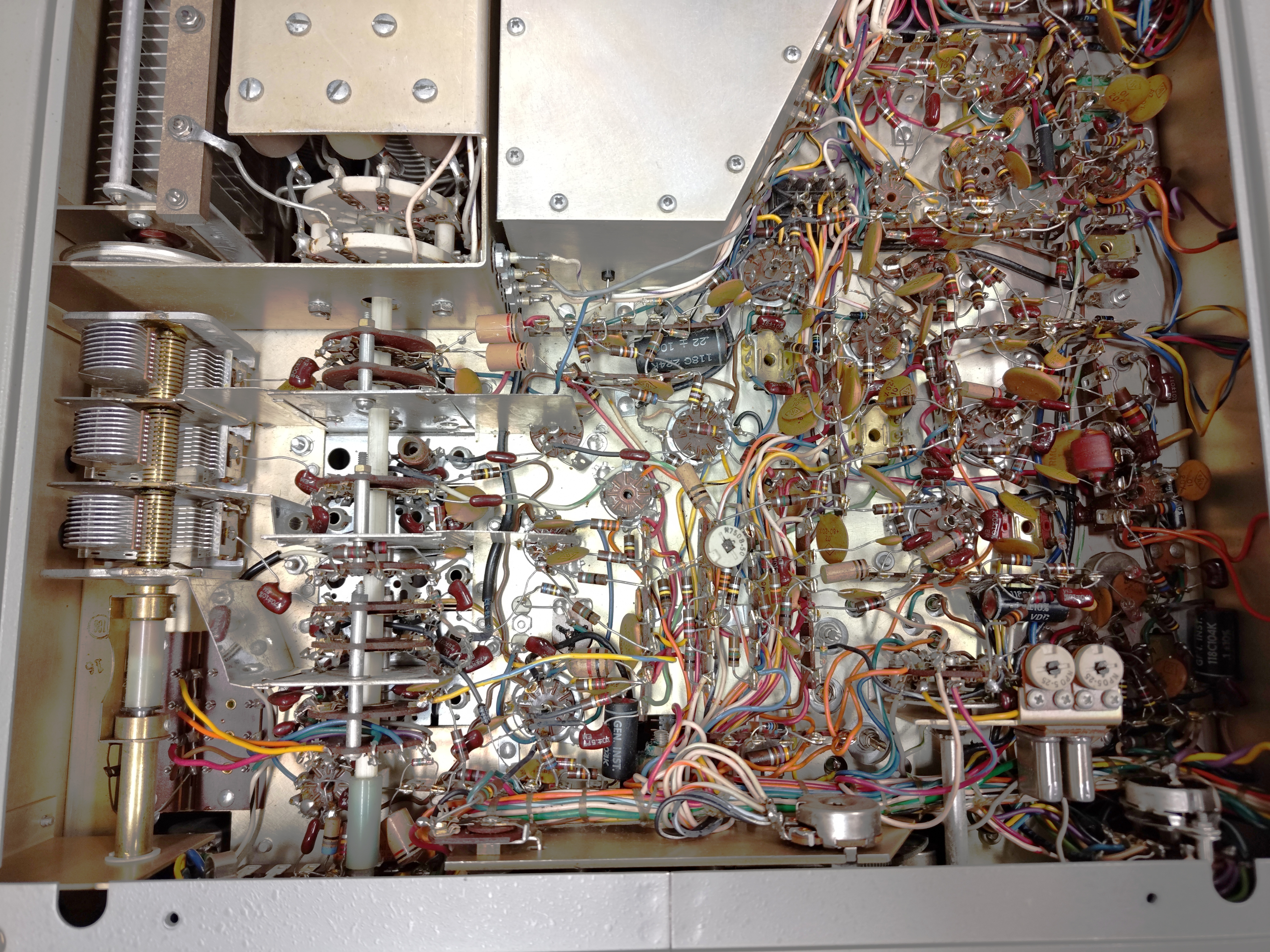
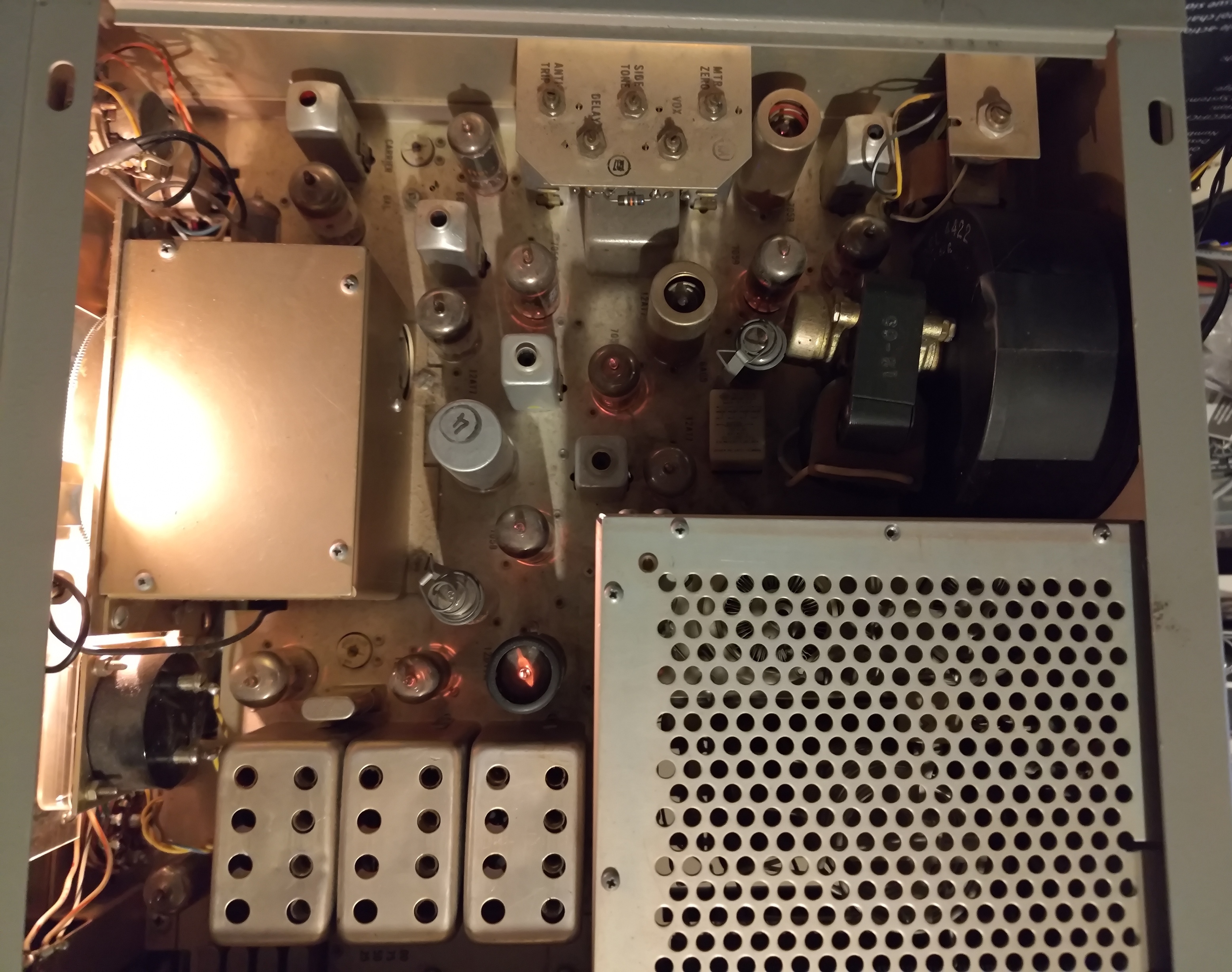
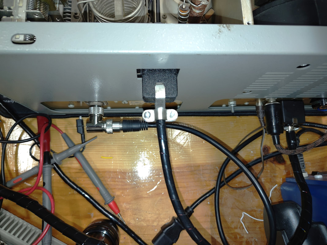
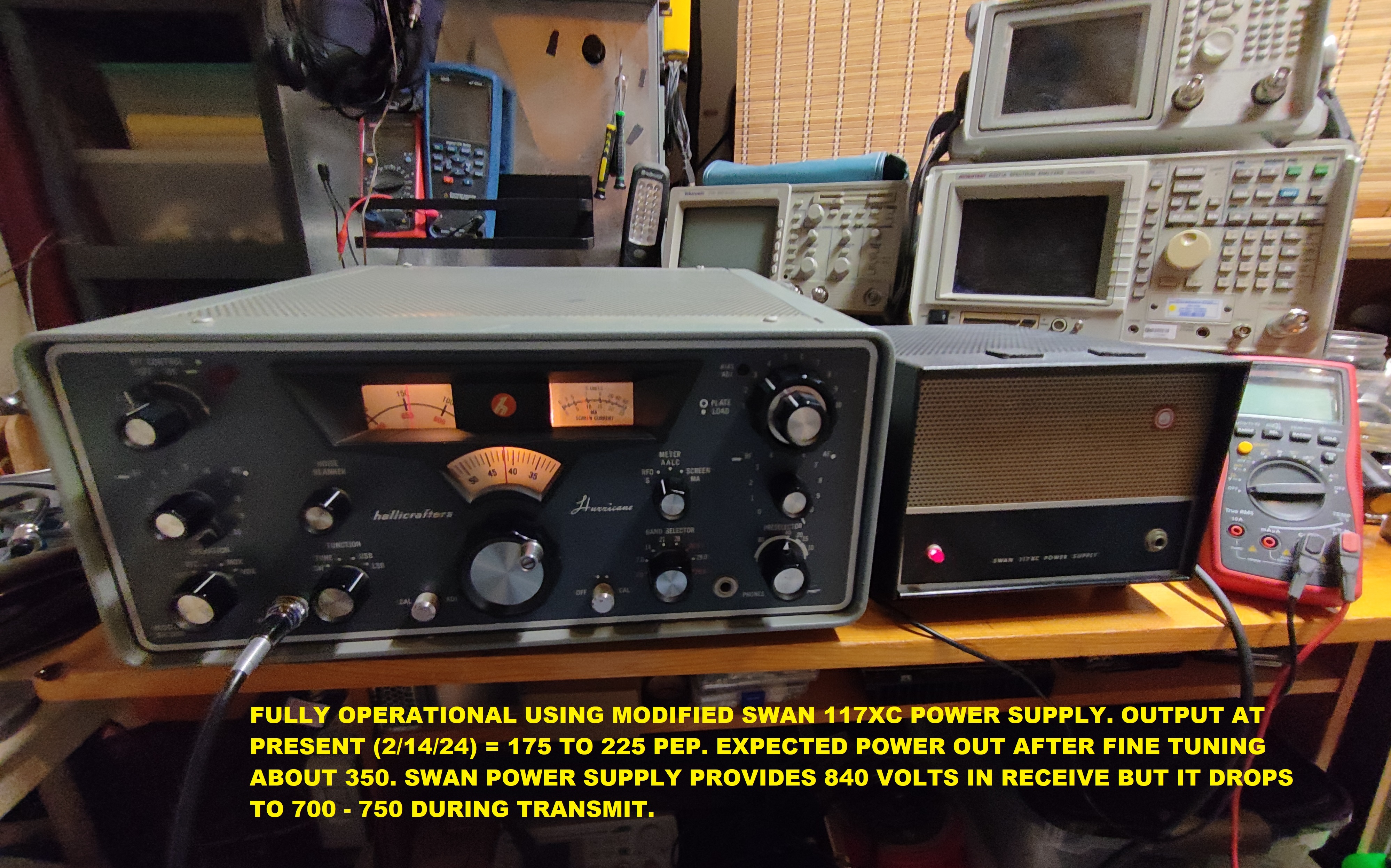
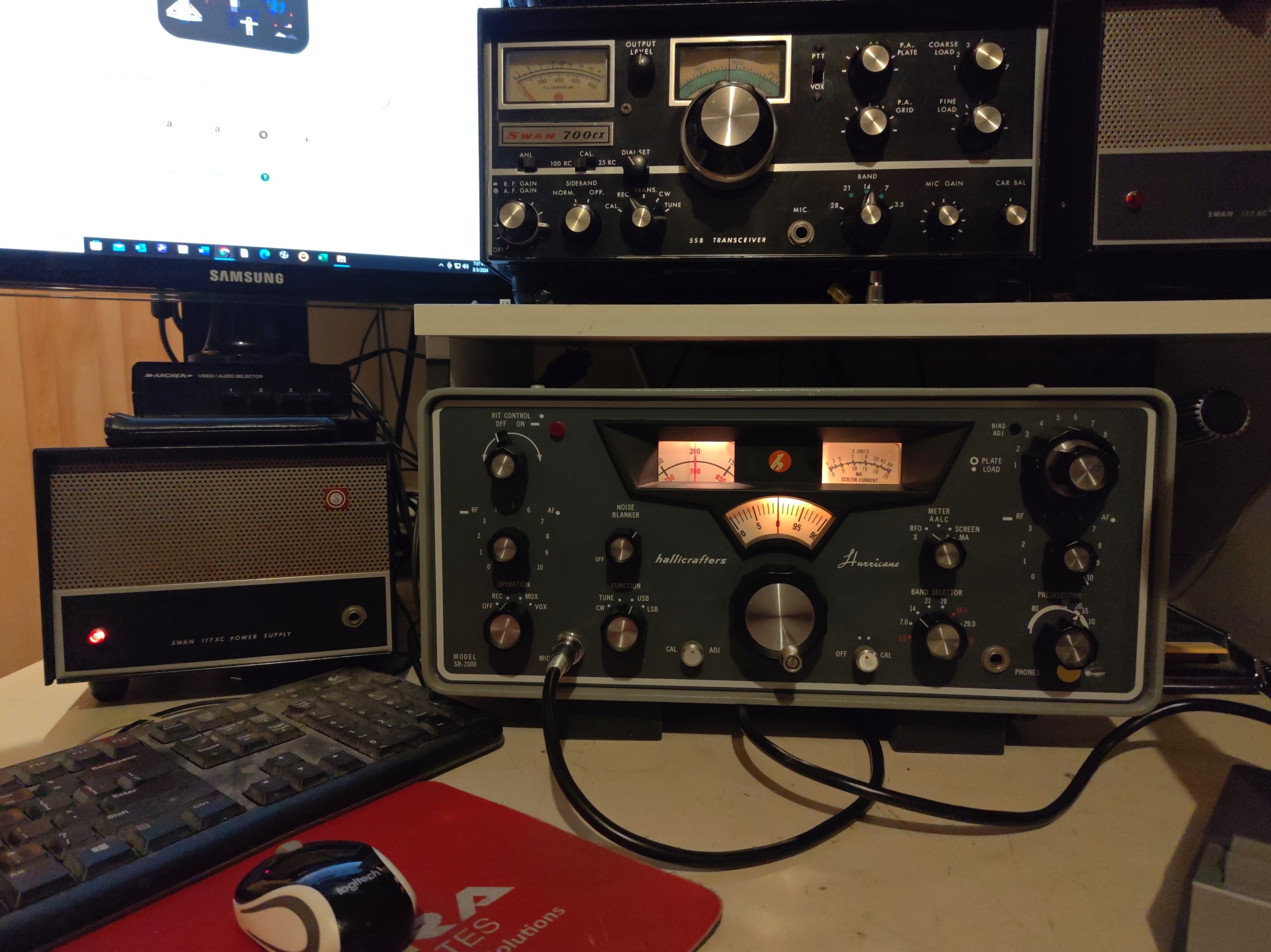
The above photos are sort of self-explanatory. The power source with the big yellow Sprague Atom capacitors is one of my Swan 117XC supplies. I modified it to work with with the Hurricane and the 800+ volts provided by the 117XC provides enough juice to drive the Hurricane to a little over 200W PEP. I've already worked Japan, Australia, and other distant QTH's with my new baby.
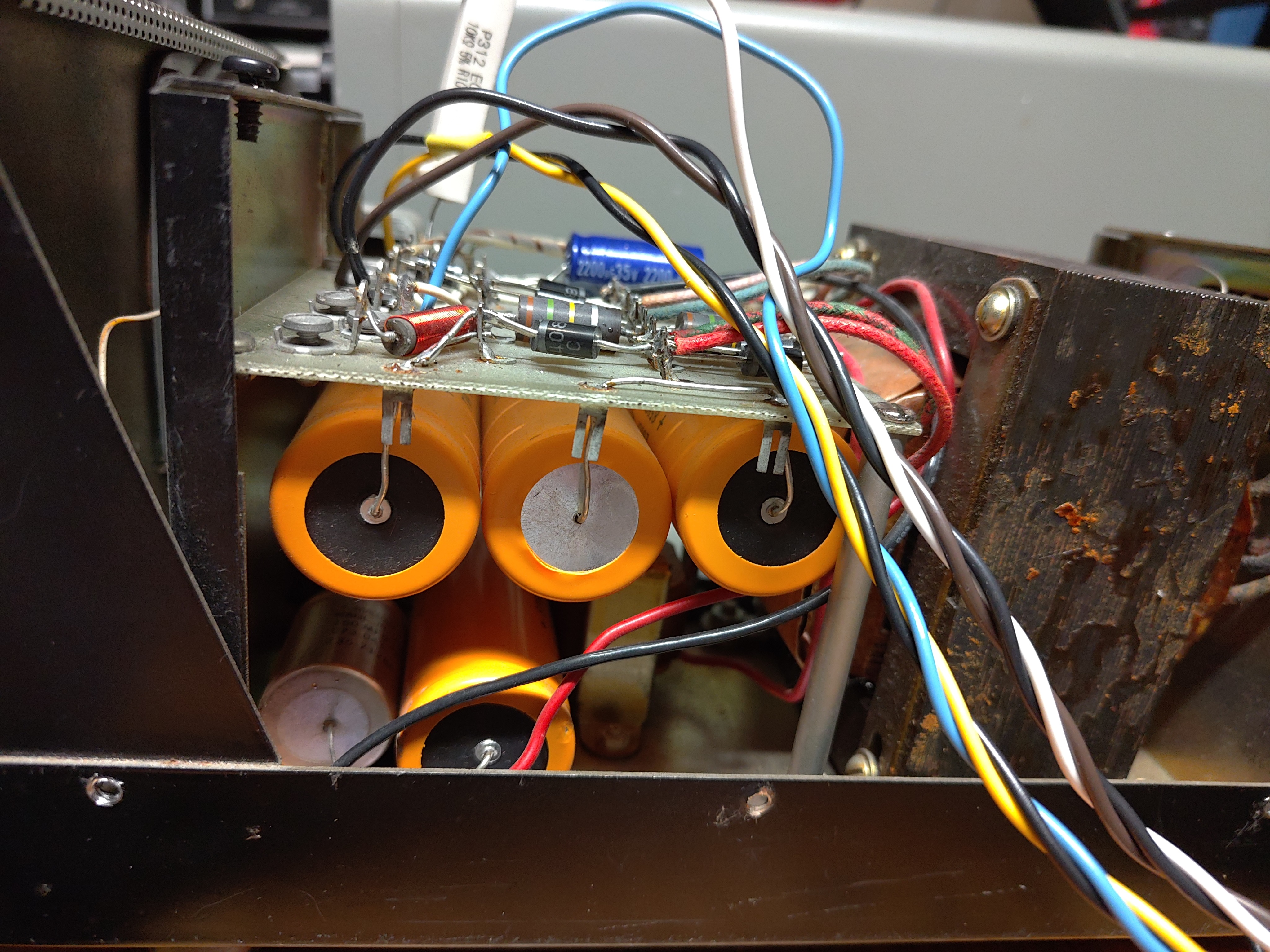
Monster Hurricane Power Supply - It Works!
I finished my big power supply, and it works great! I'm working on a schematic diagram for it now. The power supply is literally two separate supplies in a single case, fed by a 12-gauge, 3-prong cord. Each transformer is a toroid made by Antek, with dual 115V primaries and dual full-voltage secondaries. The power switch for the high voltage section is a DPDT switch that switches the primaries between series and parallel, to switch between low (1000-1100 volts) and high voltage (2,000-2200 volts) output.
Most of the time I use the Low Voltage mode, which yields a leisurely 300-350 watts PEP - more than enough to make contacts all over the planet. I get "great audio" reports. High power (photo below) bounces the power meter up over 600 watts which allows me to break through pileups easily. I still have a couple circuits to connect, but basically it's complete.
Most of the time I use the Low Voltage mode, which yields a leisurely 300-350 watts PEP - more than enough to make contacts all over the planet. I get "great audio" reports. High power (photo below) bounces the power meter up over 600 watts which allows me to break through pileups easily. I still have a couple circuits to connect, but basically it's complete.


ADAPTERS
INPUT FILTERS
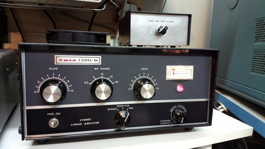
I embarked on a project to build and test various lowpass filters for the input circuit for the SWAN/Cygnet 1200-series linear amplifiers. My test bed is on the far left.
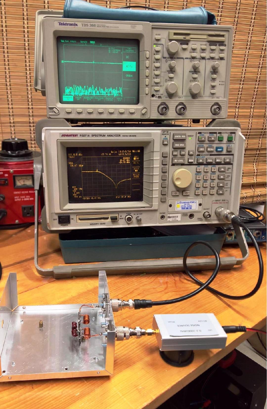
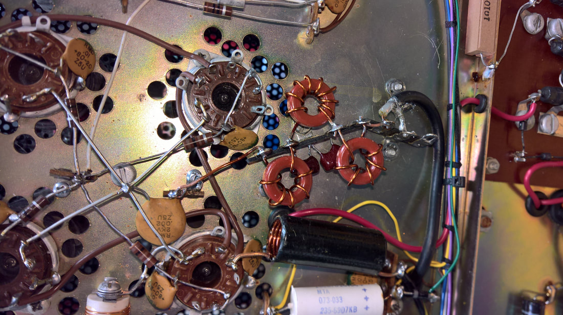
My first filter was a huge disappointment. I should mention that the Palomar LPF that I took from a TX-5200 amp and put in a metal box gave almost total isolation between the TS-930S and the amplifier. Once the autotuner in my Kenwood 930S finished adjusting itself, the SWR was 1:1 or very close and when I fine-tuned the plate and load controls on my 1200-W, the autotuner did not move, or it rarely did. Part of that might be related to the cables and other variables, but I wanted to find a good internal solution. After several basic 2nd or 3rd order filters failed to perform satisfactorily, I installed a 4:1 balun under the lower deck as shown in the pdf called "Input circuit ideas for the 1200-W", below. The balun worked well, but since it was basically a transformer, fine-tuning the amp caused the autotuner to hunt for a new match, so I started looking at multi-section filters.
NOTE: If you plan to feed your 1200-W with an assortment of rigs, including rigs with tubes and pi-networks like a Kenwood TS-830S or Yaesu FT-101 series hybrid, the balun is probably the most competent overall solution.
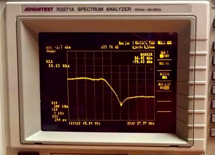
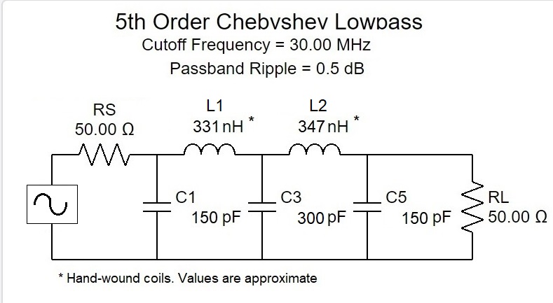
TRIAL #1: The filter I made was a copy of the "Russian" filter that I bought. It showed great promise. It's shown above in the two pictures to the right. The response curve, showing the cutoff frequency, can be seen in picture four.
PROS:
1. Rolloff started right at 30 MHz, with a curve that was identical to that of the Russian filter.
2. Super low insertion loss. Approximately 0.5 dB
3. Very low series resistance. 0.1 Ohm.
4. Transferred the most power to the amp. 450-500W PEP output on 20M from the 1200-W. The output with the balun was about 400.
CONS:
1. Only worked on 20M. Couldn't find a stable match on 40M or other bands.
2. Didn't isolate the Kenwood autotuner from cathode circuit harmonics. The autotuner "hunted" whenever I fine-tuned the 1200-W.
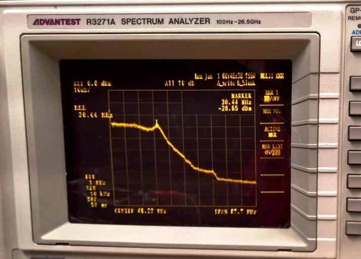
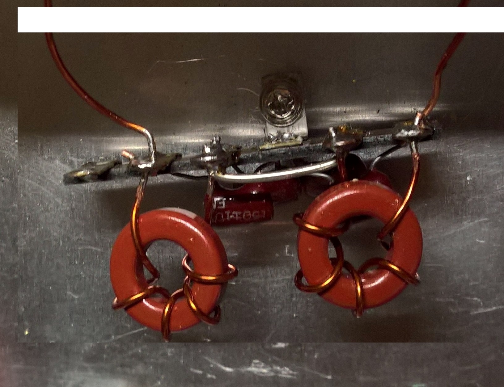
TRIAL # 2: This one is similar to the one found in the 10-15M section of the Palomar amp, except that I hand-wound toroid coils instead of using air-core. I also diverged a little bit from the Palomar design as far as the inductor values are concerned.
The first run used the Palomar values, but that one didn't start rolling off the upper end until it reached 36 MHz. I wanted it lower, so I decided to use the calculator used at a website called RF Tools - LC Filter design tool. This is a very handy website. The RF Tools calculator recommended higher values for the inductors than my first run.
The filter and setup below works for me, 80 and 40 meters find a flat match almost immediately, and fine tuning the amp doesn't cause the 930S autotuner to hunt. Interestingly, 20 meters takes 5-10 seconds to find a match, but when it does, it's almost flat. 15 meters also locks in quickly, with excellent power out. Even 10M works, but the autotuner has to hunt a bit. Here are some pictures. Note that I also cut in a chassis-mount non-polarized switched AC outlet for the fan, and I converted the RCA jack for the switching system to a chassis mounted jack. The existing grommeted hole is a little large for the jack, so I used a couple washers. The Swan 1200 series switch system is negative ground, so it doesn't need to be insulated from the chassis.
PROS:
1. Rolloff started at 29.5 MHz, with a curve that more closely resembles a Type 2 / inverse Chebyshev filter (ripples in the stop band).
2. Super low insertion loss. Approximately 0.5 dB
3. Very low series resistance. 0.1 Ohm.
4. Transferred as much power to the amp as the "Russian" filter.
5. Autotuner lock in immediately on the 80, 40, and 15 meter bands.
CON: Doesn't completely isolate the Kenwood autotuner from cathode circuit harmonics. The autotuner "hunts" a little when I
fine-tune the 1200-W on 20 and 10M.
NOTE: If you plan to feed your 1200-W with an assortment of rigs, including rigs with tubes and pi-networks like a Kenwood TS-830S or Yaesu FT-101 series hybrid, the balun is probably the most competent overall solution.
TRIAL #1: The filter I made was a copy of the "Russian" filter that I bought. It showed great promise. It's shown above in the two pictures to the right. The response curve, showing the cutoff frequency, can be seen in picture four.
PROS:
1. Rolloff started right at 30 MHz, with a curve that was identical to that of the Russian filter.
2. Super low insertion loss. Approximately 0.5 dB
3. Very low series resistance. 0.1 Ohm.
4. Transferred the most power to the amp. 450-500W PEP output on 20M from the 1200-W. The output with the balun was about 400.
CONS:
1. Only worked on 20M. Couldn't find a stable match on 40M or other bands.
2. Didn't isolate the Kenwood autotuner from cathode circuit harmonics. The autotuner "hunted" whenever I fine-tuned the 1200-W.
TRIAL # 2: This one is similar to the one found in the 10-15M section of the Palomar amp, except that I hand-wound toroid coils instead of using air-core. I also diverged a little bit from the Palomar design as far as the inductor values are concerned.
The first run used the Palomar values, but that one didn't start rolling off the upper end until it reached 36 MHz. I wanted it lower, so I decided to use the calculator used at a website called RF Tools - LC Filter design tool. This is a very handy website. The RF Tools calculator recommended higher values for the inductors than my first run.
The filter and setup below works for me, 80 and 40 meters find a flat match almost immediately, and fine tuning the amp doesn't cause the 930S autotuner to hunt. Interestingly, 20 meters takes 5-10 seconds to find a match, but when it does, it's almost flat. 15 meters also locks in quickly, with excellent power out. Even 10M works, but the autotuner has to hunt a bit. Here are some pictures. Note that I also cut in a chassis-mount non-polarized switched AC outlet for the fan, and I converted the RCA jack for the switching system to a chassis mounted jack. The existing grommeted hole is a little large for the jack, so I used a couple washers. The Swan 1200 series switch system is negative ground, so it doesn't need to be insulated from the chassis.
PROS:
1. Rolloff started at 29.5 MHz, with a curve that more closely resembles a Type 2 / inverse Chebyshev filter (ripples in the stop band).
2. Super low insertion loss. Approximately 0.5 dB
3. Very low series resistance. 0.1 Ohm.
4. Transferred as much power to the amp as the "Russian" filter.
5. Autotuner lock in immediately on the 80, 40, and 15 meter bands.
CON: Doesn't completely isolate the Kenwood autotuner from cathode circuit harmonics. The autotuner "hunts" a little when I
fine-tune the 1200-W on 20 and 10M.
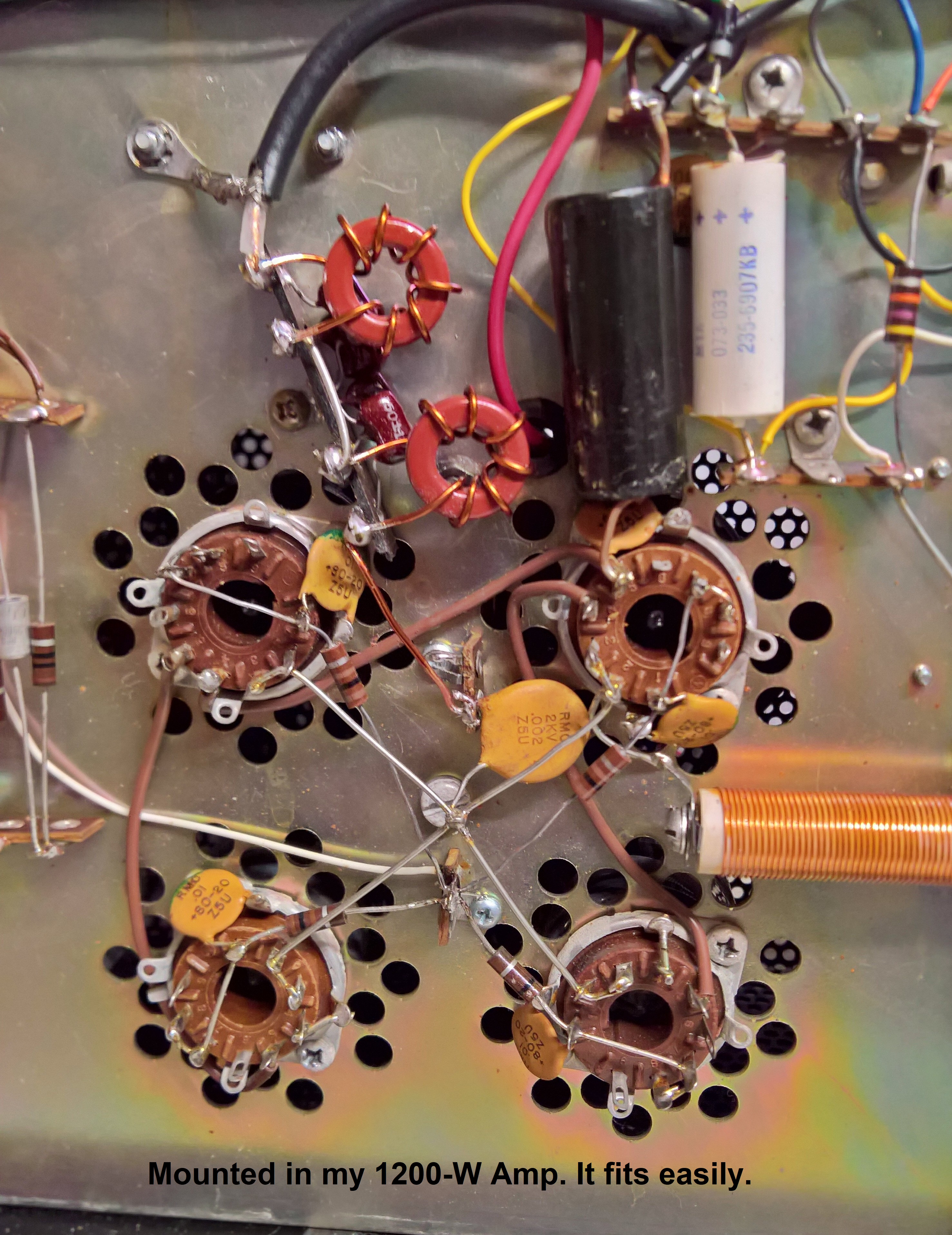
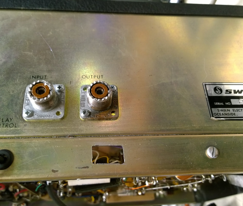
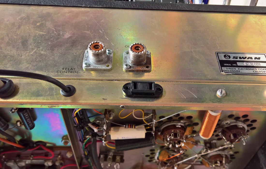
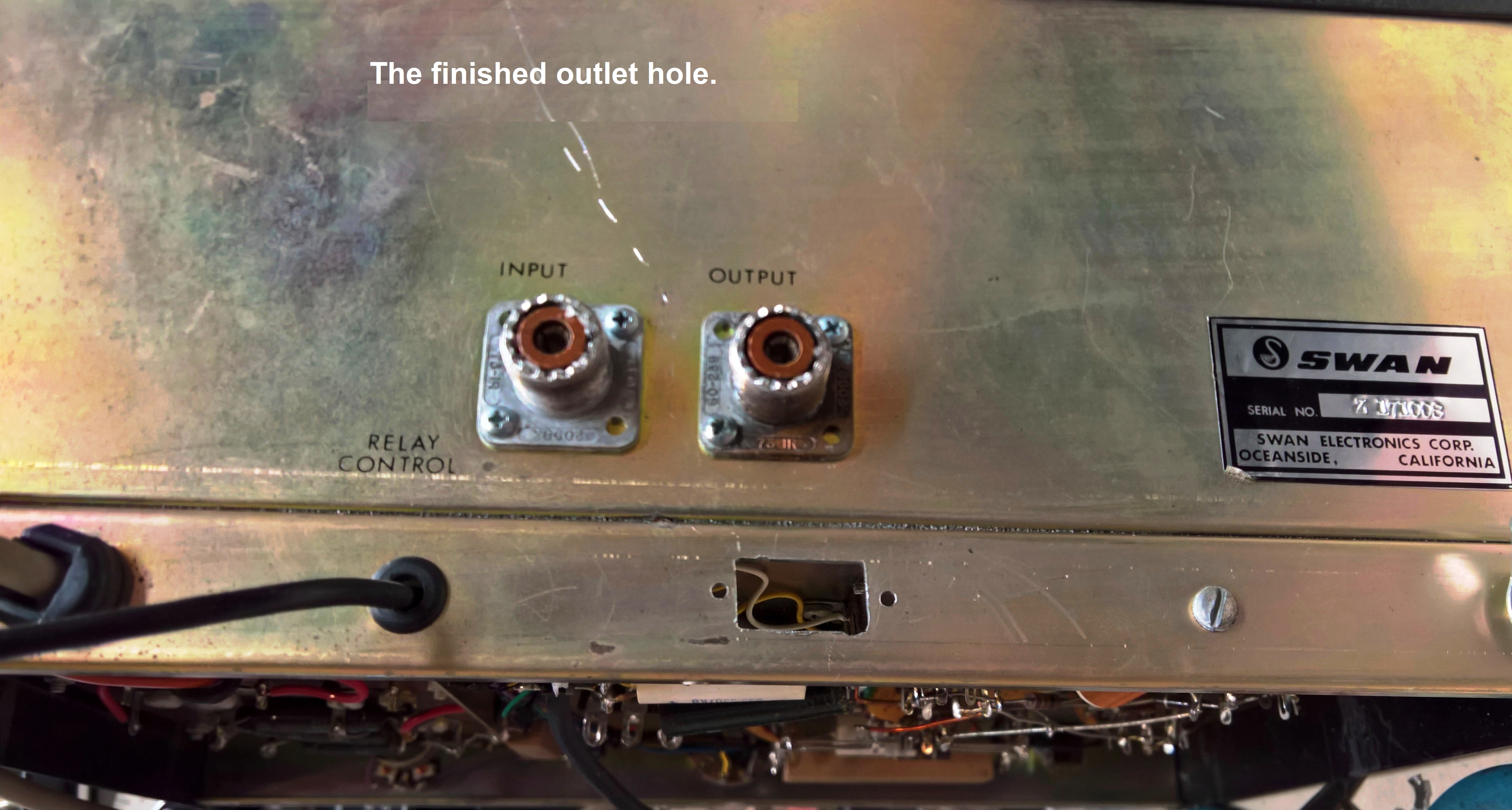
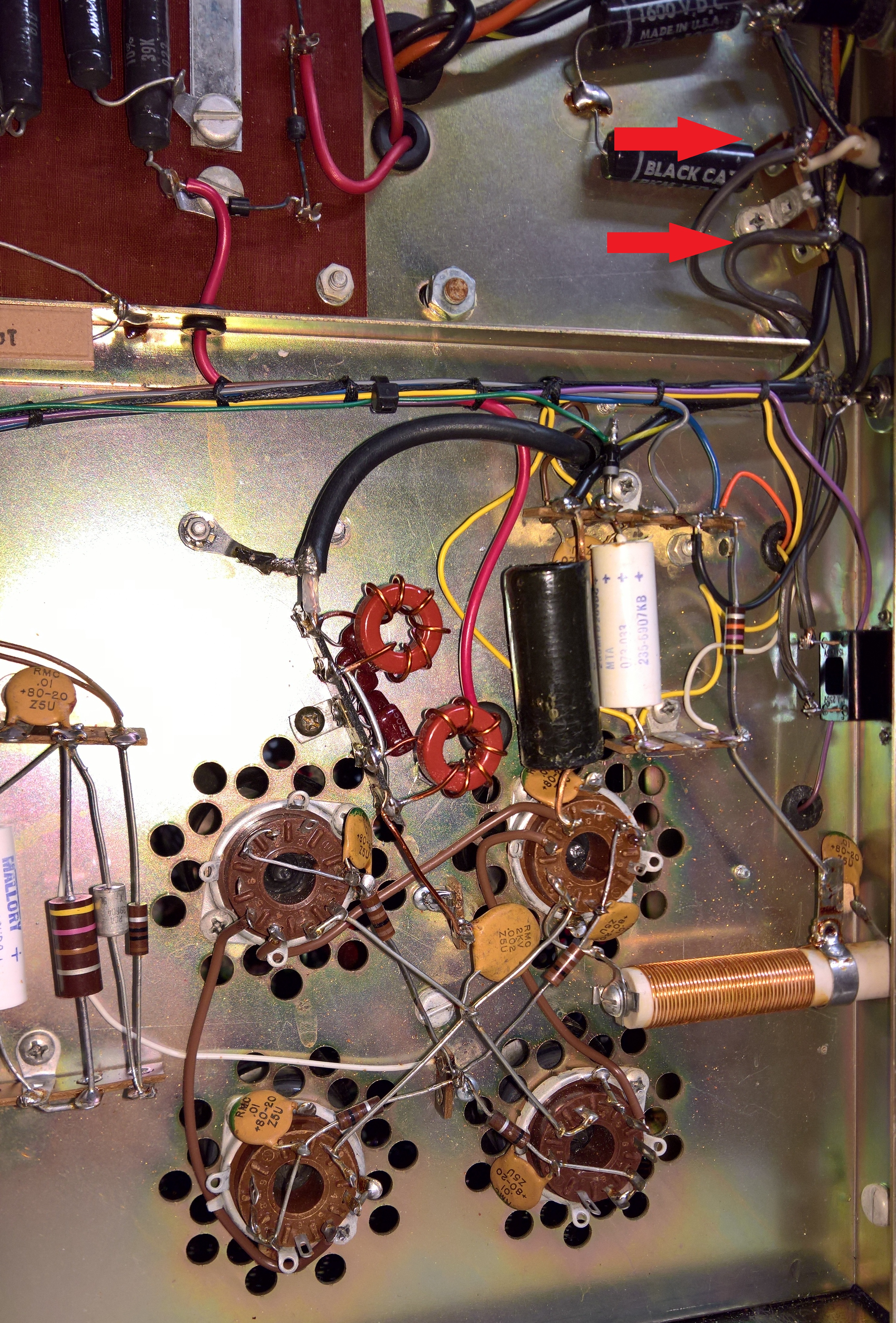
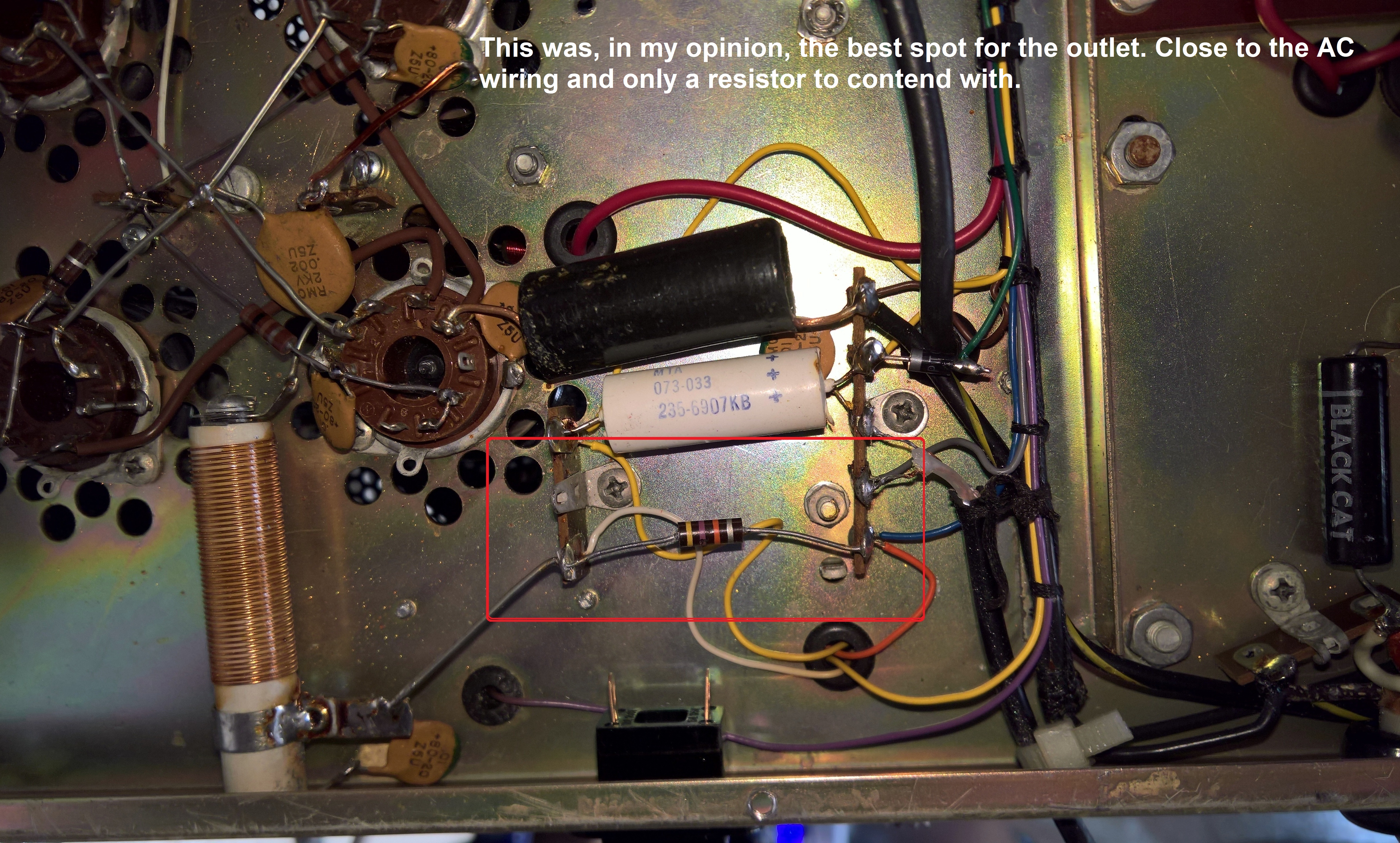
ADD A SWITCHED OUTLET TO THE 1200-W AMP
For those who are interested, here's how and where I added a switched outlet for a cooling fan. I didn't want to cut a big hole in the back of the amp housing. I did that on a Palomar tube linear, and while it does work, it's a huge headache, and it doesn't cool as well as a top-mounted fan. It's important to find a place where there's enough room, while avoiding tuned circuits. I used a readily-available Philmore R118J AC outlet in case I ever need to replace it. The wires from the outlet go to the terminal strip with the red arrows.


SWAN TRANSCEIVER SECTION
TUBE TESTING INFORMATION
TEST EQUIPMENT REVIEWS
With all the inexpensive test equipment out there, i thought it would be fun to buy a few pieces, test them, and put some "semi-scientific" reviews here. I started with a cheap "Arbitrary Waveform" Sweep-Function Generator, and now I'm adding an inexpensive but popular DMM called the WH5000A that's sold under a couple brand names, including AstroAI, and Kuman. I bought the AstroAI version, which boasted a frequency counter capability of 60MHz. Impressive young Skywalker, but you are not a Jedi yet.
I also just finished playing with a JinHan JDS2012A handheld oscilloscope/DMM combo. The advertised scope bandwidth is 20MHz, but its response extends far beyond that. In fact, it can display the 44.93MHz First IF frequency of the 930S Signal Unit. The review is below, but I have many more photos of this scopemeter at work to add. I use mine daily.
I also just finished playing with a JinHan JDS2012A handheld oscilloscope/DMM combo. The advertised scope bandwidth is 20MHz, but its response extends far beyond that. In fact, it can display the 44.93MHz First IF frequency of the 930S Signal Unit. The review is below, but I have many more photos of this scopemeter at work to add. I use mine daily.
other useful information, SCHEMATICS, MANUALS, ETC
EQUIPMENT NAMEPLATES: I found a company on eBay that makes very nice nameplates, and they made a couple for my radios. Their name is Players Trophies and Awards.


