A PAGE DEDICATED TO TRANSISTOR TESTERS OLD AND NEW
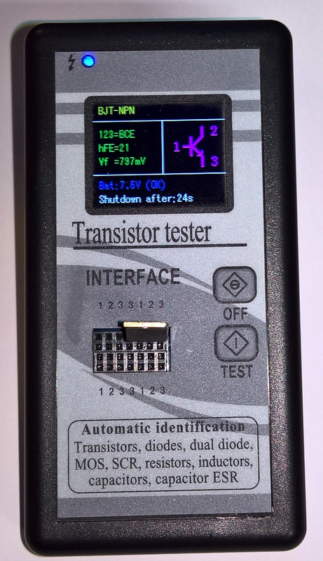
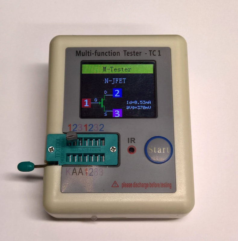
NOTE: I just purchased the new, popular Multi-Function Tester-TC1. I thought it would have something different because it has such great reviews, and it had a micro-USB port. But that's only for charging the battery. There's no PC connectivity whatsoever.
It DOES have the capability of testing Zener diodes up to 30-volts. However, I haven't found a way to make it show the regulated voltage. More to come on this device and the others.
Transistor testers are like tube testers - every tech needs one, and some need five or six. In this section, I will set forth on a quest to find the Holy Grail of testers. Some test at low voltages and currents, and others use as much as 4.5 volts. The factory tests many power transistors like the MRF-485 at 5 volts, and 5 amperes. That high current doesn't make sense to me, but that's what their specs claim. Can all the testers agree on things like gain (hFE)? That's what I plan to find out.
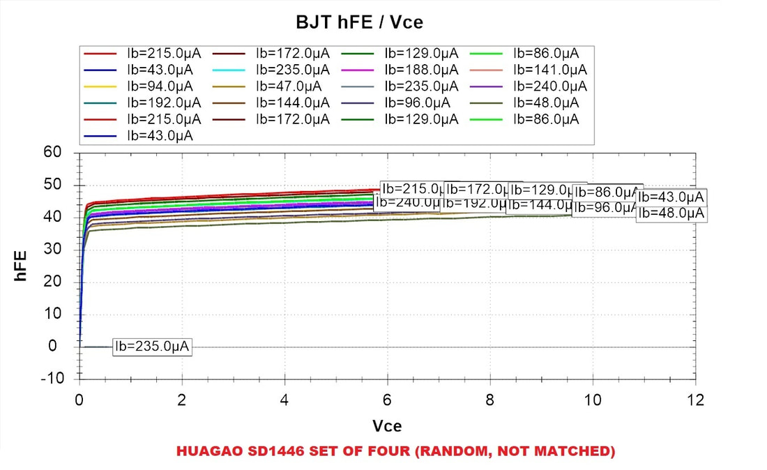
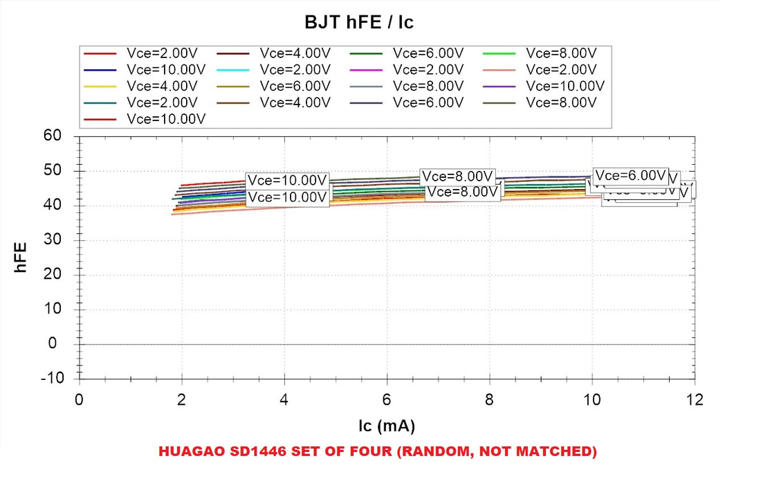
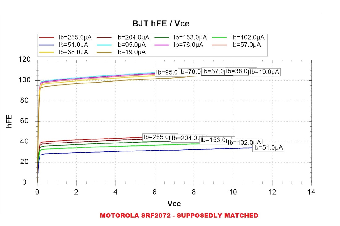
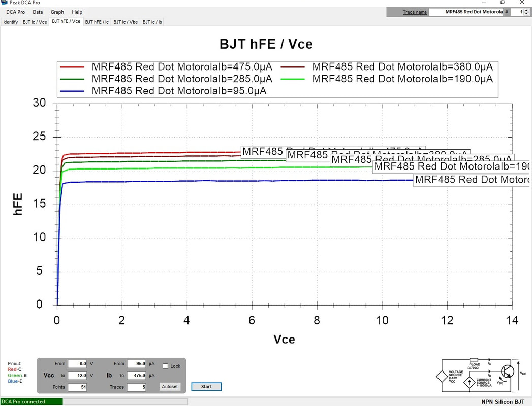
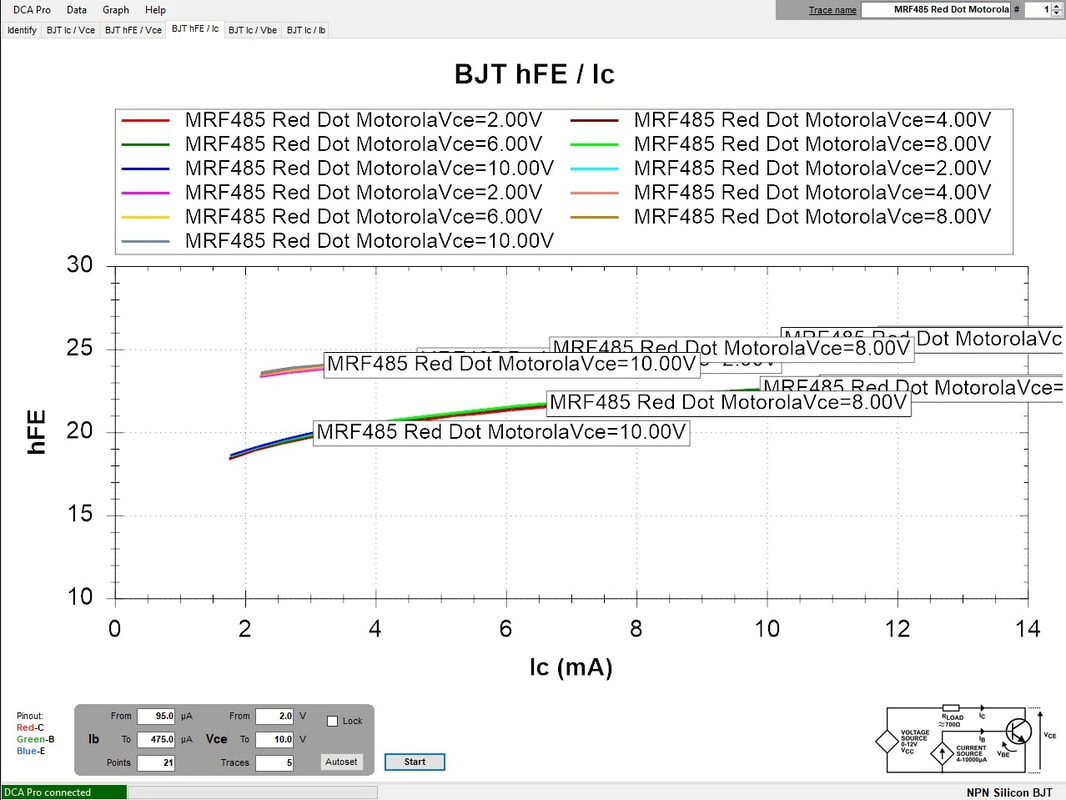
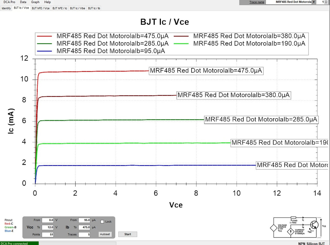
Step 1 is to test a group of transistors using my PEAK DCA75 analyzer with PC graphing and create curve tracings with that. The DCA75 tests at the lowest voltage of all my testers, and then extrapolates curves based on the principle that the gain of a silicon junction is fairly linear, so after a certain voltage and current level, the gain will be uniform up to the point of junction failure.
For those of you who just want something simple, cheap, durable, and very effective, skip down to "The King of Simple - DROK"
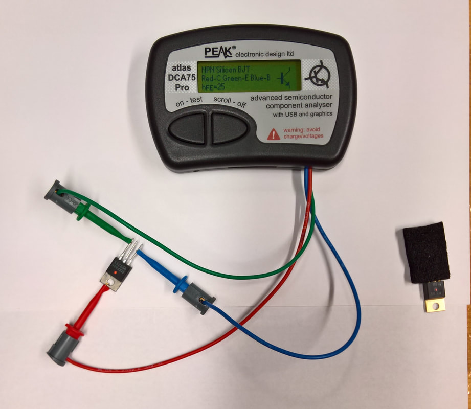
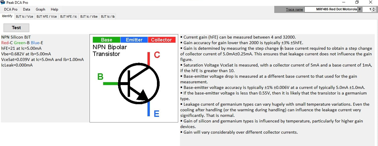
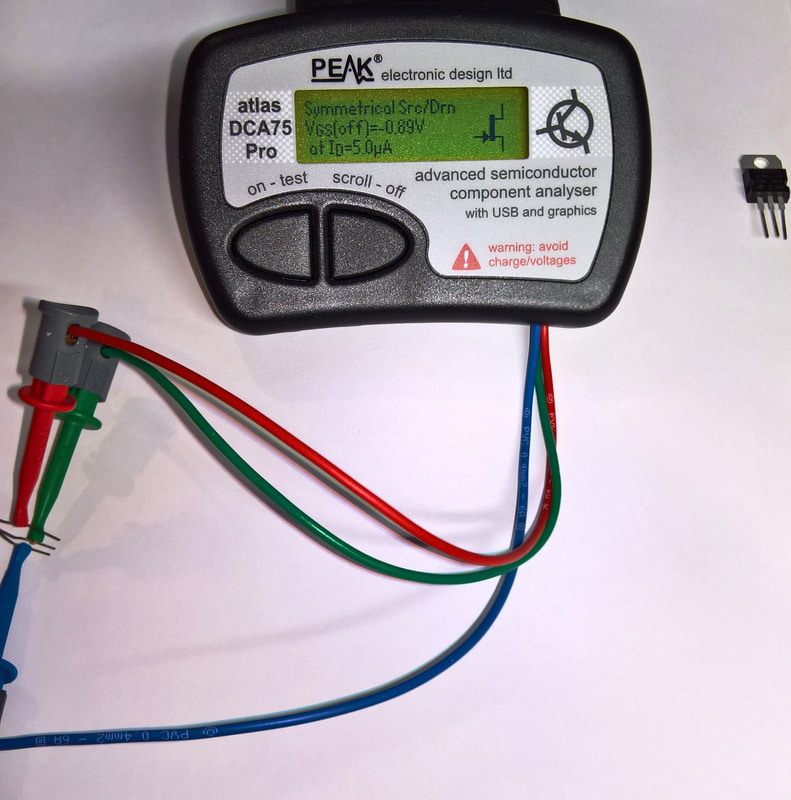
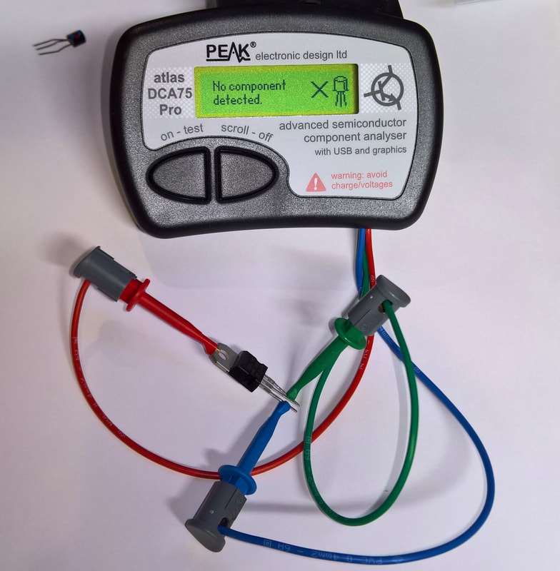
PEAK DCA75 "ADVANCED SEMICONDUCTOR ANALYZER"
At a cost of $159.00, this is the most expensive tester in my workshop. It's built like a toy, but it identifies many devices automatically regardless of how the leads are attached, and it creates useful performance curves as shown below which I plan to use to compare to the results that I get with the other testers. It also uses the smallest battery from a B+ perspective: 1.5 volts. Note that the values for Vce in the graphs greatly exceed that voltage, so this device must use an algorithm to predict the hFE and other parameters at higher voltages based on the rate of change in the junction. Maybe the Fundamental Theorem of Calculus?
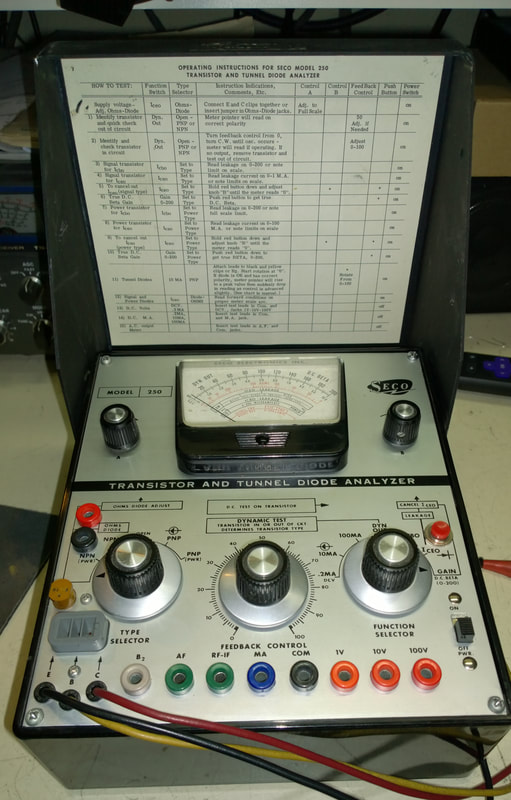
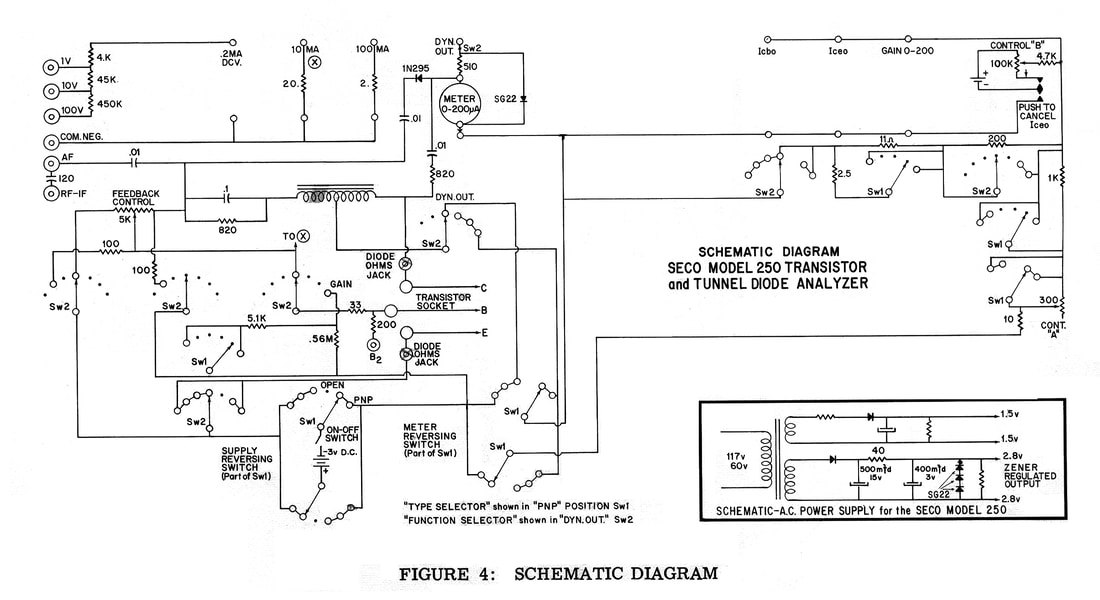
SECO 250 TRANSISTOR TESTER
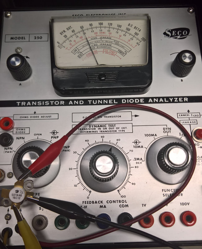
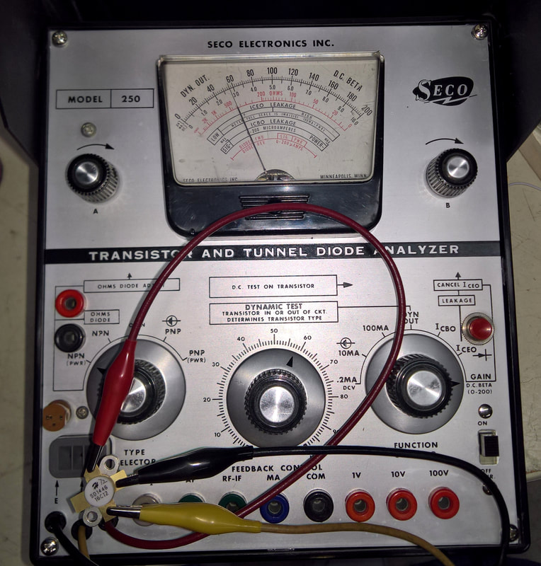
The SECO 250 Transistor and Tunnel Diode Analyzer applies a higher Vce than the DCA75 - close to 3 volts. The Model 250 has lots of knobs and dials and is fun to operate. It typically requires that the user know or at least have an idea of what device they are working with, although the 250, as well as ones like the Sencore Super Cricket can identify the type of device under test. Some photos are below. It was in unusually clean condition when I bought it.
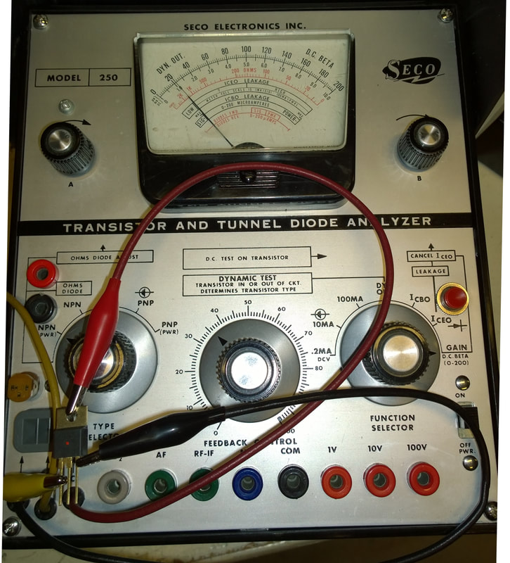
One of the cool things about the SECO 250 is its ability to test transistors in circuit. It applies a signal via the "Feedback" control. If the transistor is shorted, open, or just plain dead - the meter won't "sweep". Capacitors and other components around a transistor stage typically won't oscillate. But if the transistor is good, the meter needle will sweep upward and then back down as the transistor oscillates. I tested that feature on an old control board from a reel deck, and a couple photos are below..
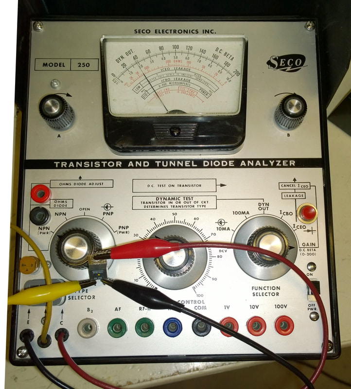
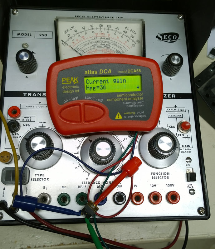
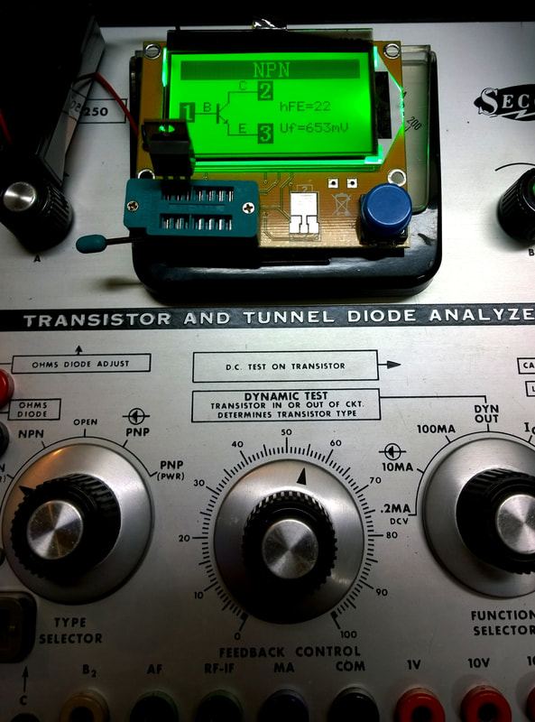
So far, the 250 is right on target as far as accuracy when compared to the Peak DCA 55, DCA 75, and other testers like the DROK and the Mega 328. A complete "bake off" will be forthcoming soon. But the pictures below give some indication of it's usefulness. The first driver transistor under test (left two pictures) below is a "yellow dot" Motorola MRF485, which has an advertised hFe (current gain) of 35-40. The last four tests are a Red Dot MRF 485 with a published gain of 18-24.
The SECO 250 test voltage (Vce) is between 2.5 and 2.8 volts, which is about 3 times as great as typical testers. More on that in awhile.
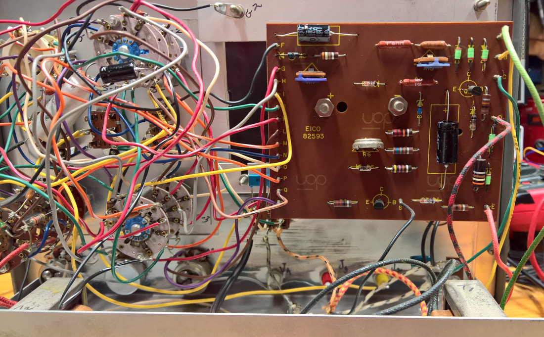
THE BUTTONS BELOW WILL TAKE YOU TO THE COMPLETE OWNER'S MANUAL WITH A DOWNLOADABLE LARGE VERSION OF THE SCHEMATIC-AND MORE WILL COME LATER.I split the manual into the main section with the instructions and schematic, and a second section which contains transistor data, because the files are so large.
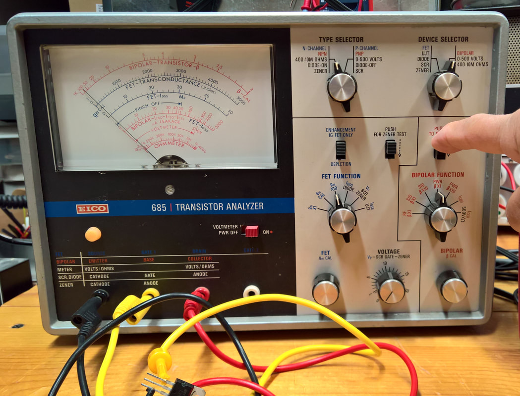
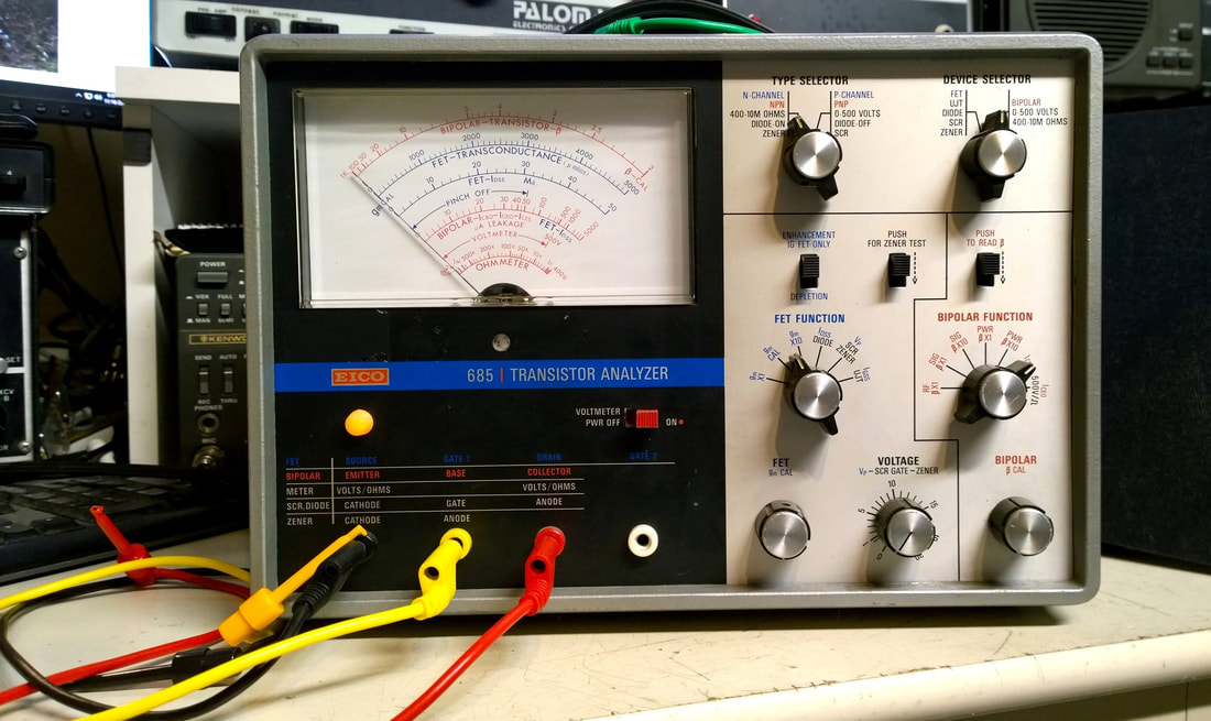
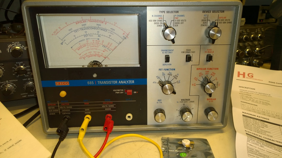
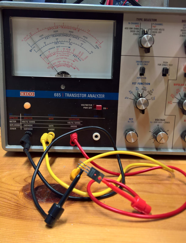
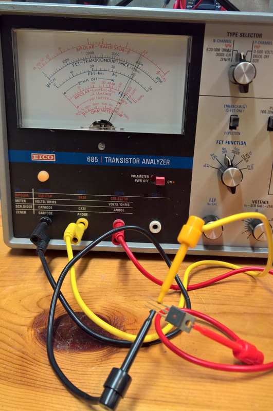
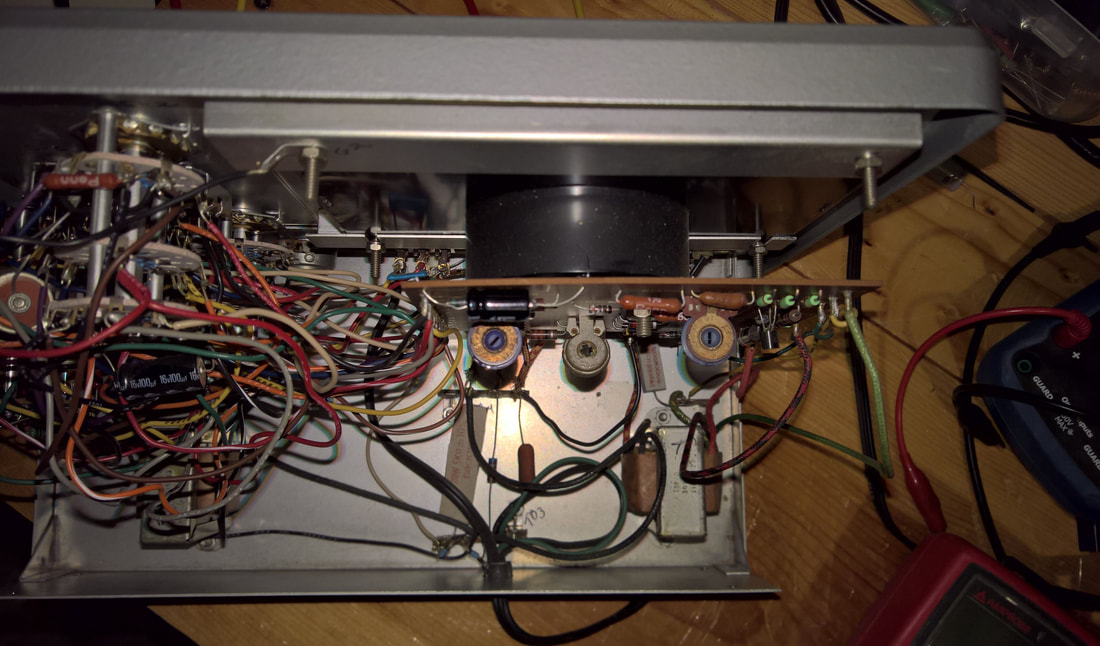
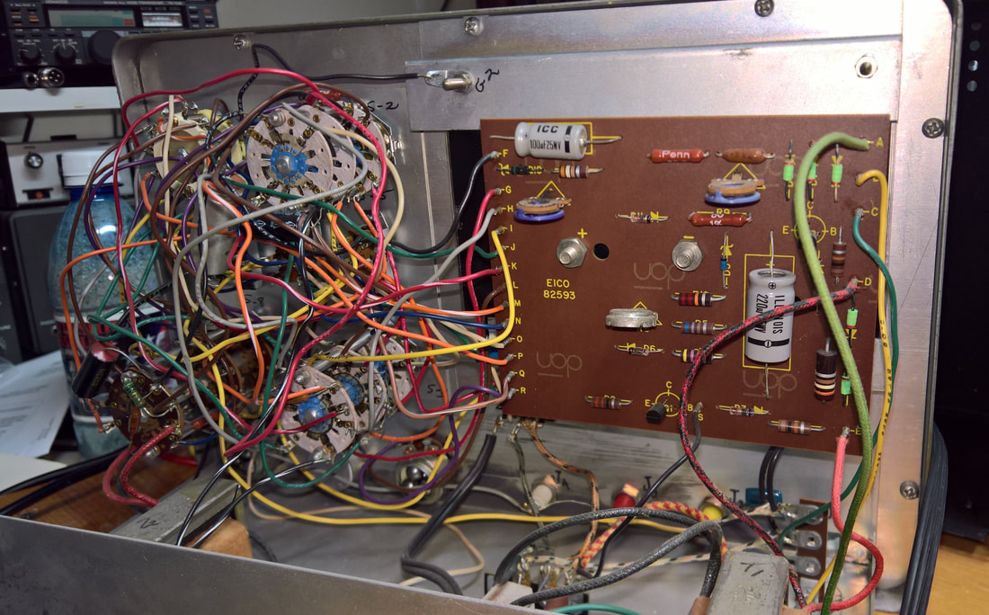
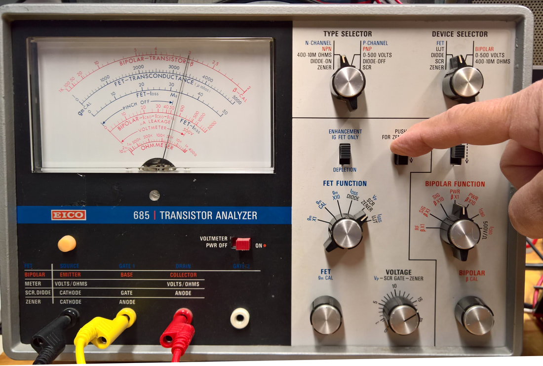
I bought this tester on eBay also. It was in very good condition, but the cabinet had some rust on it. I sanded it down and repainted it, cleaned the electronics, and made some nice test leads. This outperforms the SECO 250 in some areas, and in others the 250 beats the EICO. Overall, this is more of an analyzer than a ready-tester although I've learned to perform Beta tests quickly. Like the SECO 250, the EICO 685 can test devices in or out of circuit.
Despite being an AC operated device, the EICO 685 imposes a Vce of only 0.7 to 0.8 volts - about the same as the PEAK DCA55 and 75 models. The results agree somewhat closely with the PEAK models.
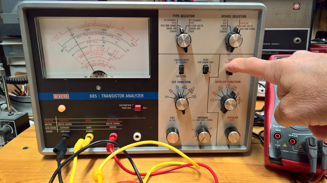
In the last photo above, the 685 is being used to verify the output voltage for an L7815CV regulator. The device is tested as an Triac. Depress the ZENER test button, rotate the VOLTAGE knob, and watch the needle till it stops advancing. That's the output voltage.
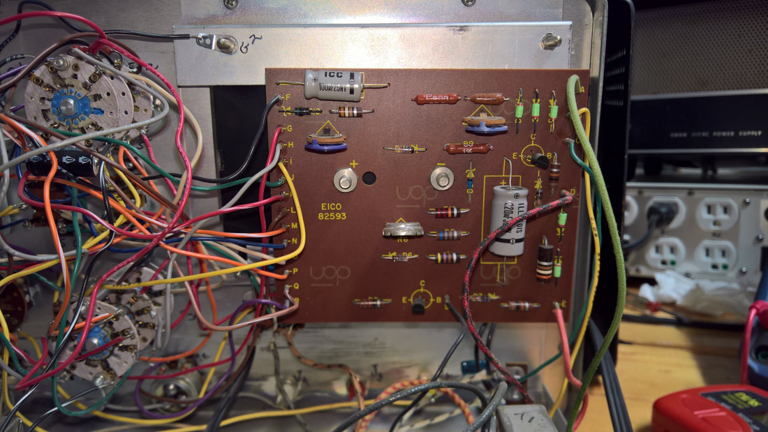
The schematic for the 685 is available on the Internet, but to save time, I show it below. I also put a button for the complete manual with this schematic below. I have the complete manual for this, but someone already did an excellent job of scanning it, so I used theirs. I had to split the manual into two parts, because when it comes to file sizes, Weebly is no better than Bluehost - unless I upgrade to a much more expensive plan.
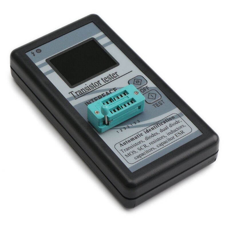
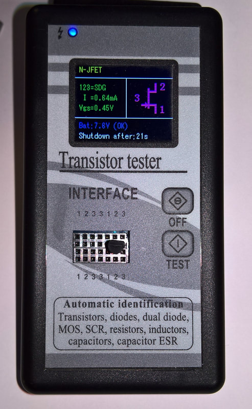
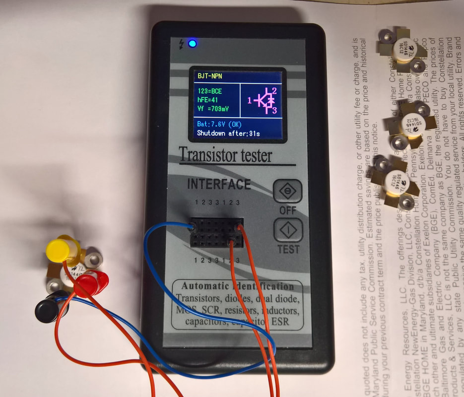
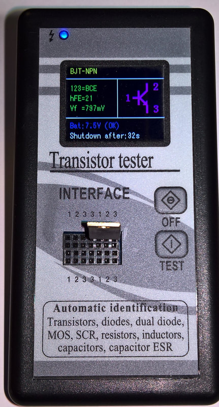
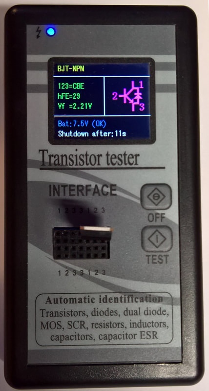
This simple device probably got the nickname "Drok" because it's sold by a company of that name. It's called by many names (B1 ESR is just one), but it's durable, it's simple, and it's as or more accurate than testers costing 3 times as much (the typical online price is about $25.00) If you need to run through (test) a bin full of transistors over the weekend, this is the one for you. Mine came with a cheap lever-operated setup, which broke almost immediately, but the unit has a push-in block with the 1,2,3 positions clearly labeled built in.
The built-in block of contacts makes it easy to plug things in, from semiconductors to capacitors. It's just so-so on inductors under 0.1 mH - it thinks they are resistors. But for everything else, it's great. The pictures below show it beating the PEAK testers on a couple devices. One is a simple L7815CV voltage regulator.
When it comes to testing regulators, the winner is - the EICO 685. It actually determines the voltage for regulators up to a max of 20V. The device is set up as a Triac Test, the Zener button is depressed, and the voltage knob advanced until the needle stops advancing. But you DO have to know what the device under test is (see the EICO section above)
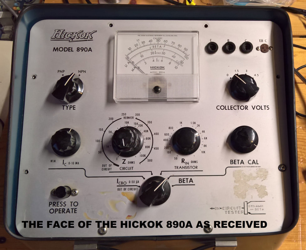
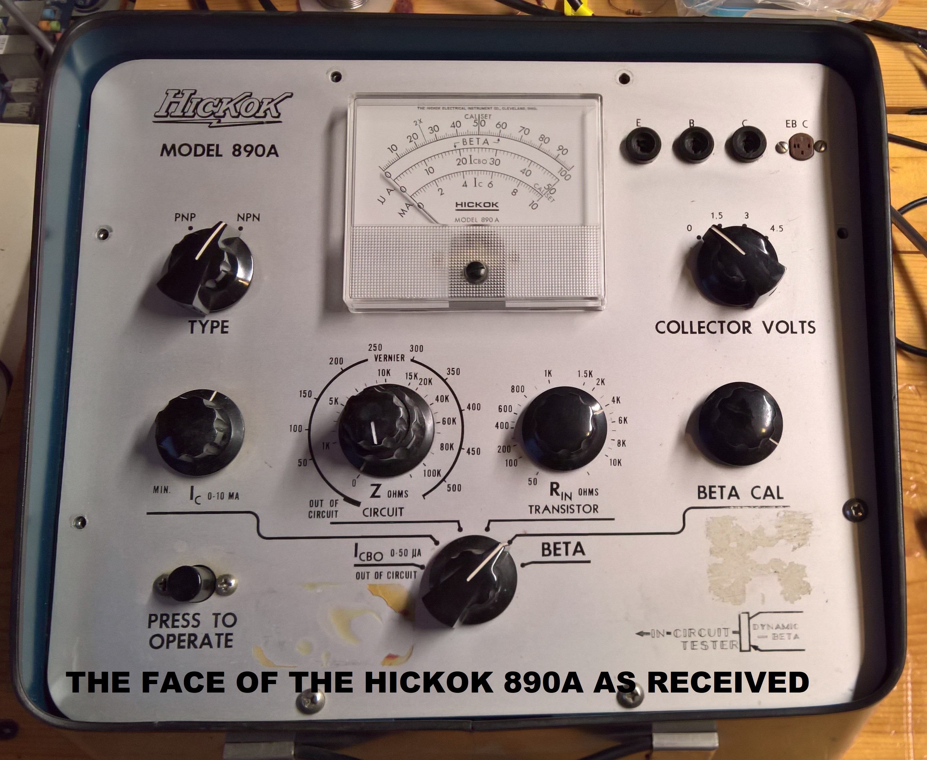
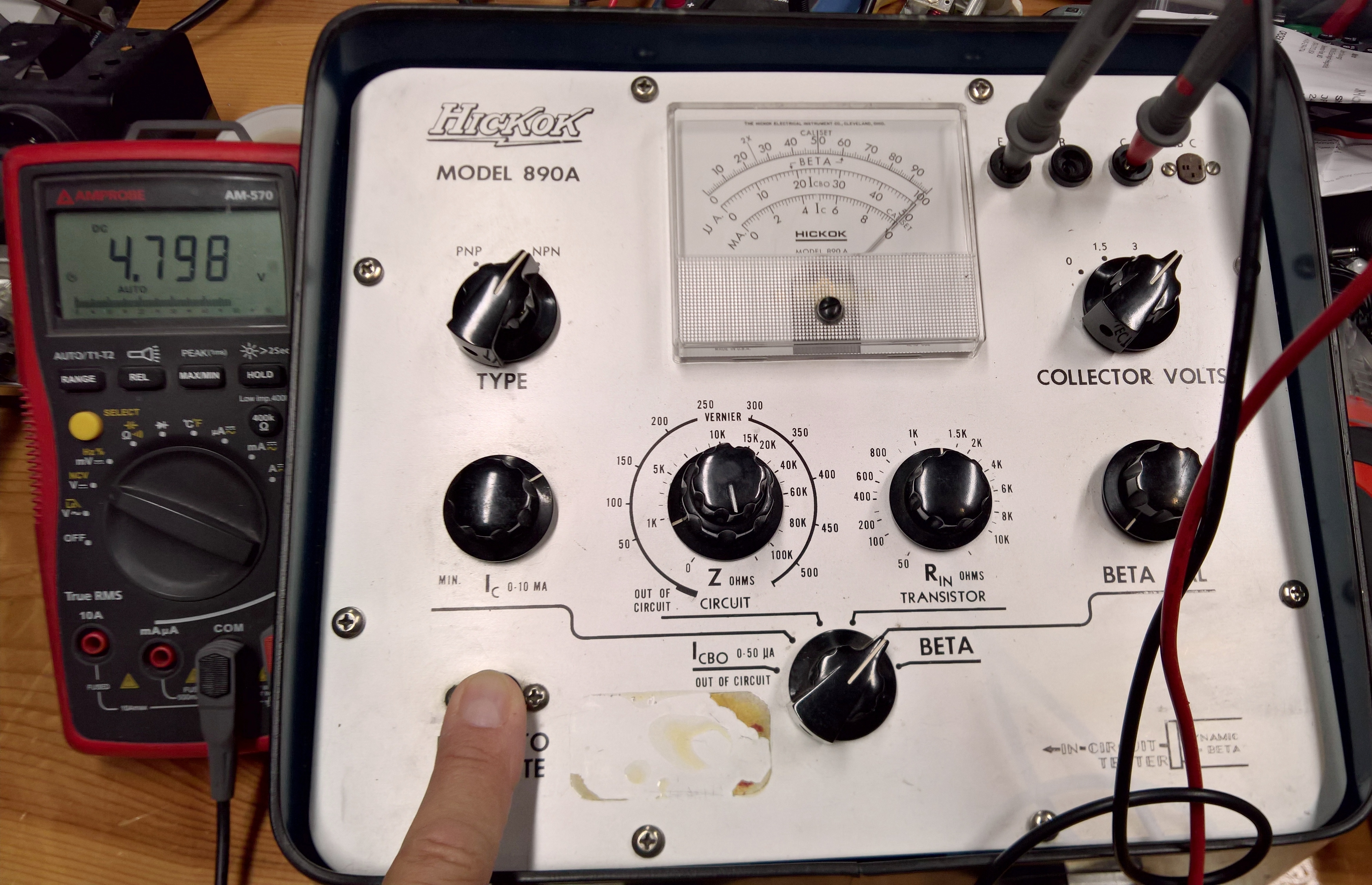
HICKOK 890A TRANSISTOR BETA TESTER
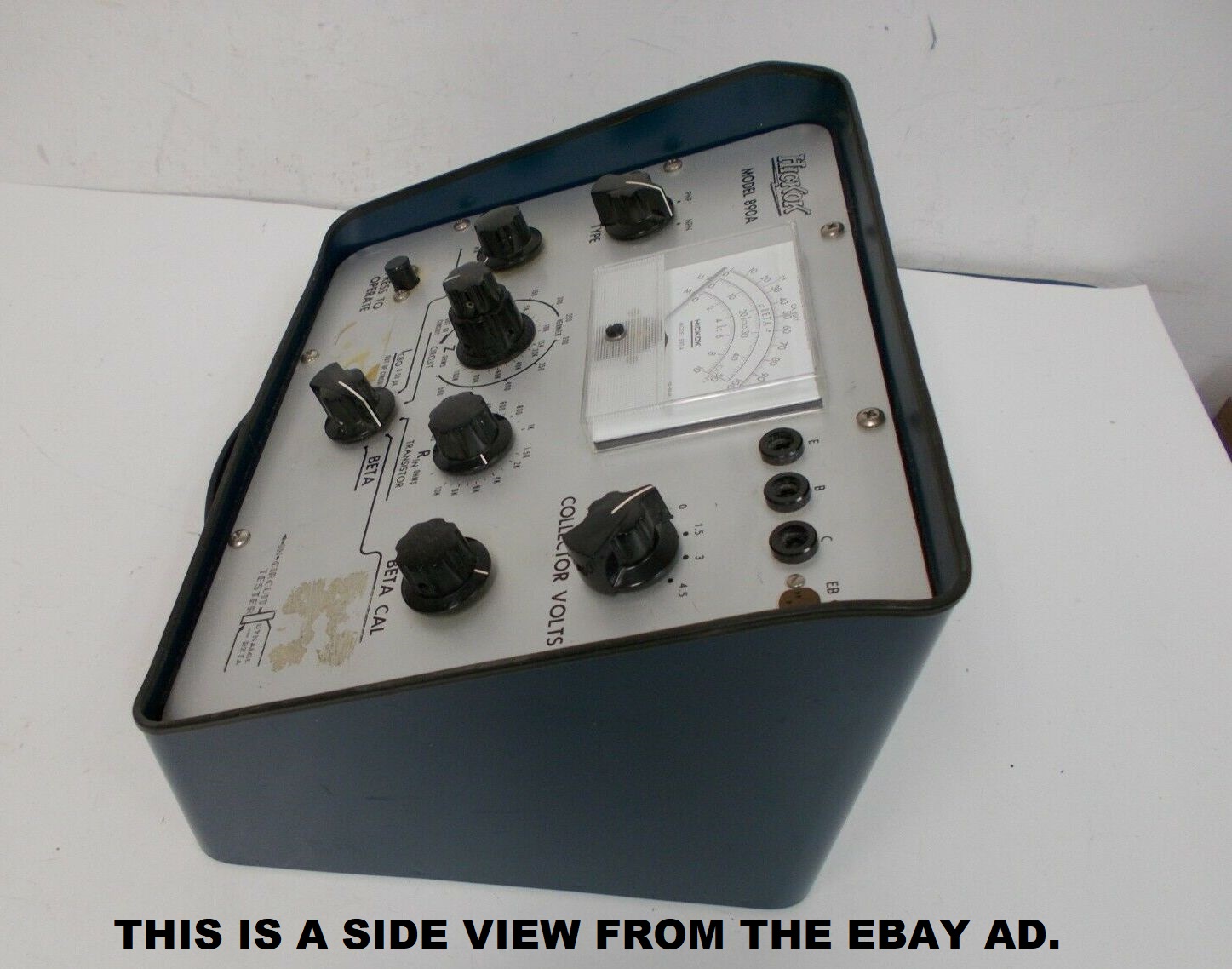
This in yet another of my eBay acquisitions. I bought it in May 2021. It was in good condition, but the battery boxes and the mounting plate had some rust. The"C"-cell boxes were so corroded they were worthless.
Like Hickok tube testers, Hickok transistor testers tend to be complicated, and this one is no exception. This is probably the second most complicated transistor tester ever sold. Their 870 series testers almost certainly hold the number 1 spot. The 870 is powered not only by the AC line but it also needs a couple batteries. Leave it to Hickok!
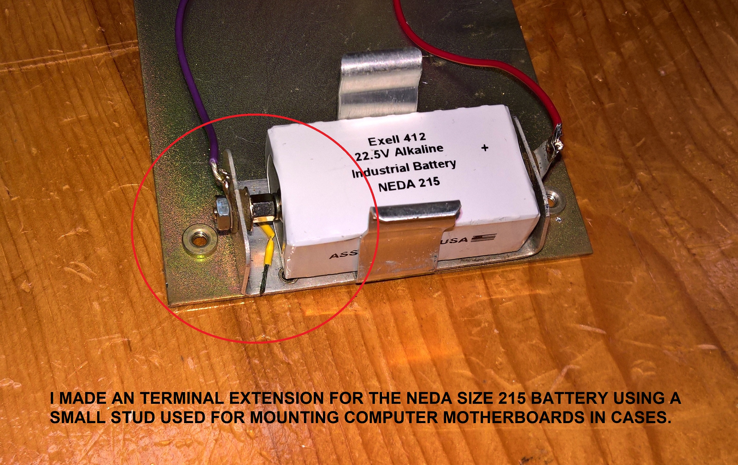
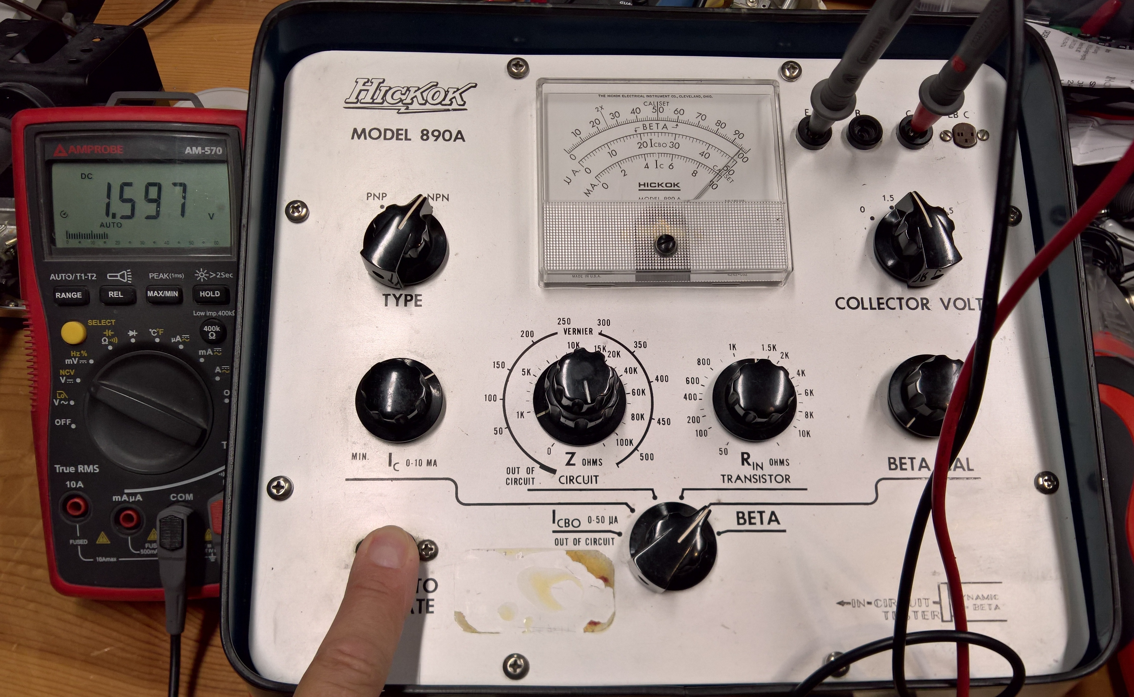
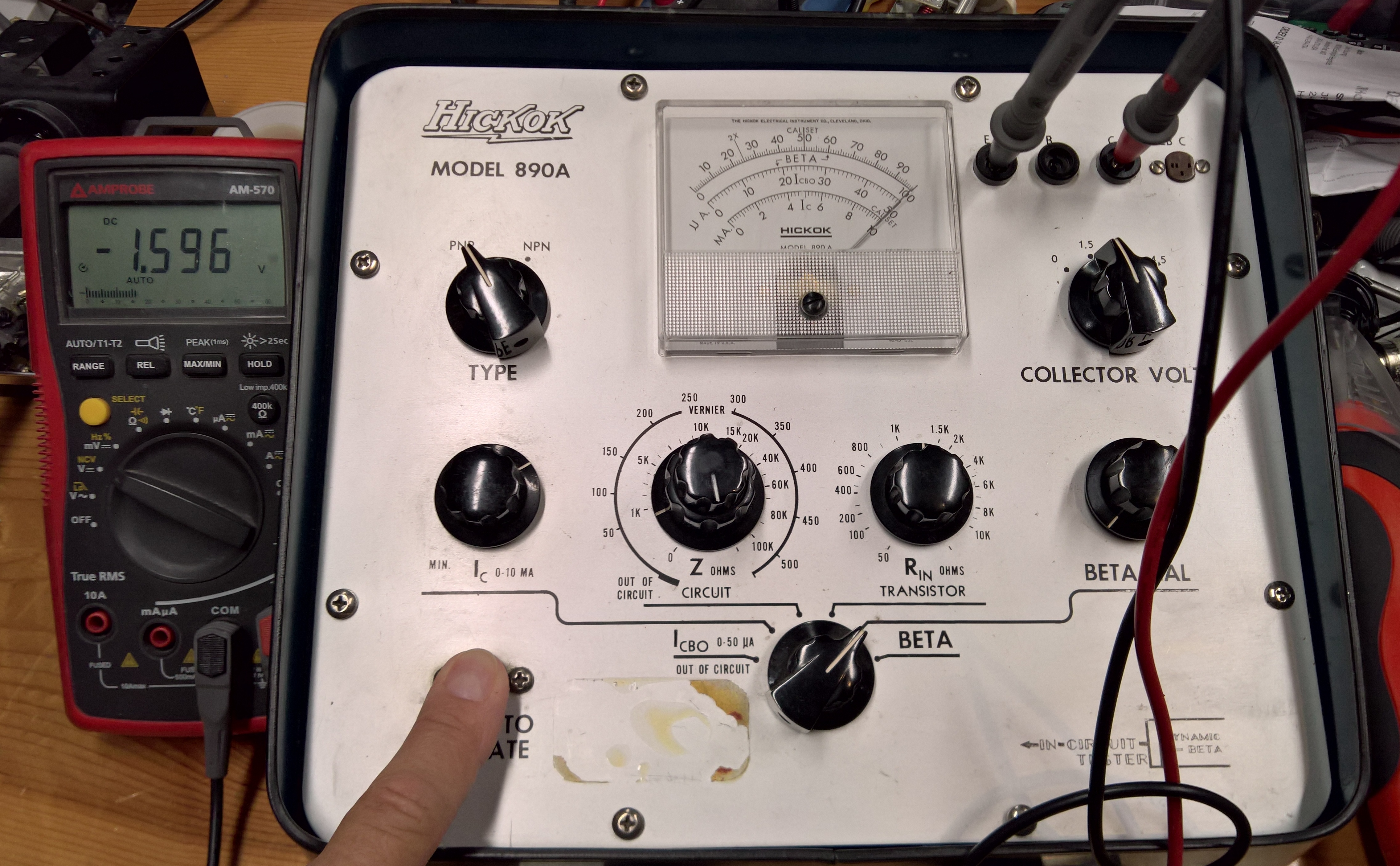
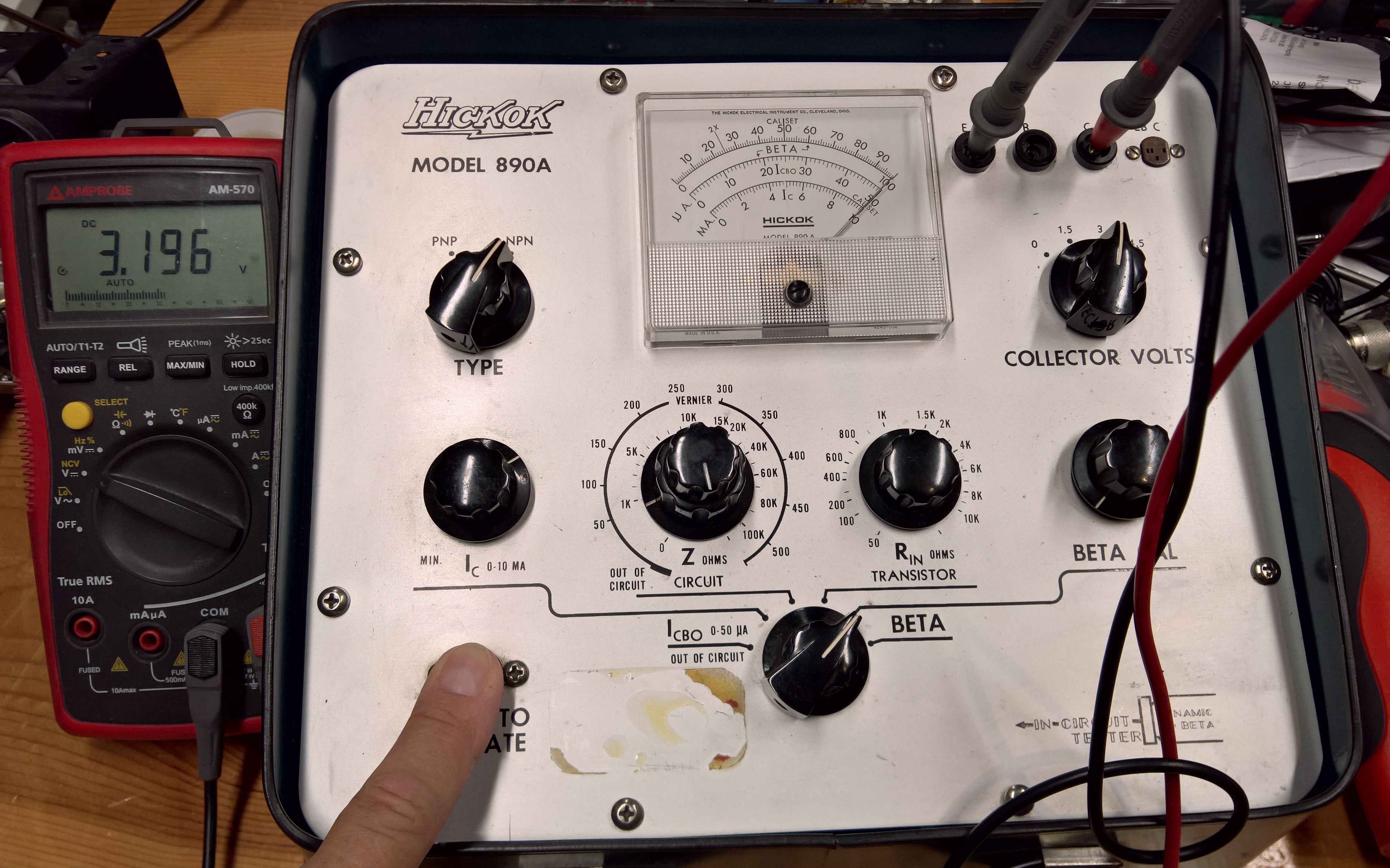
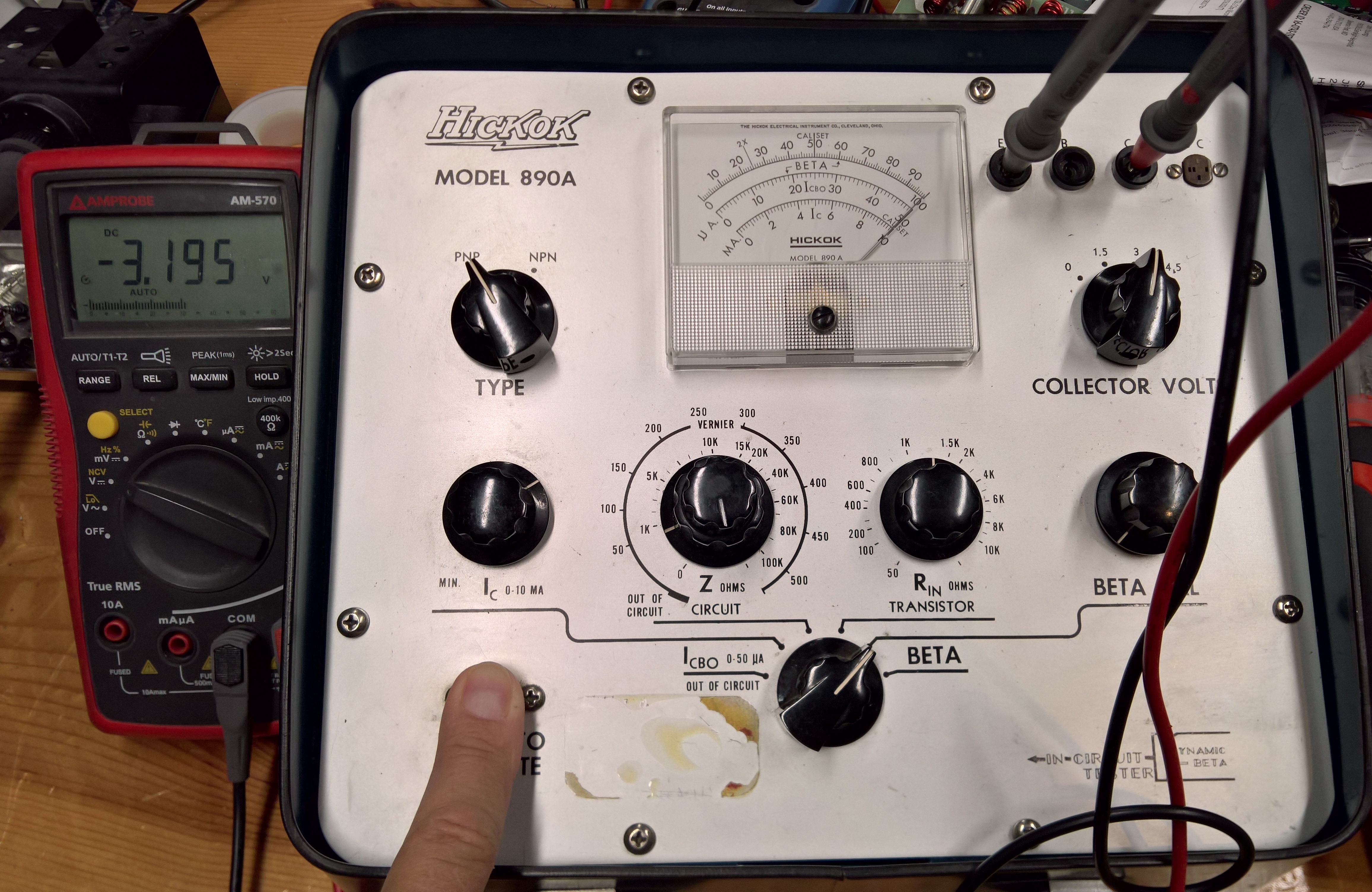
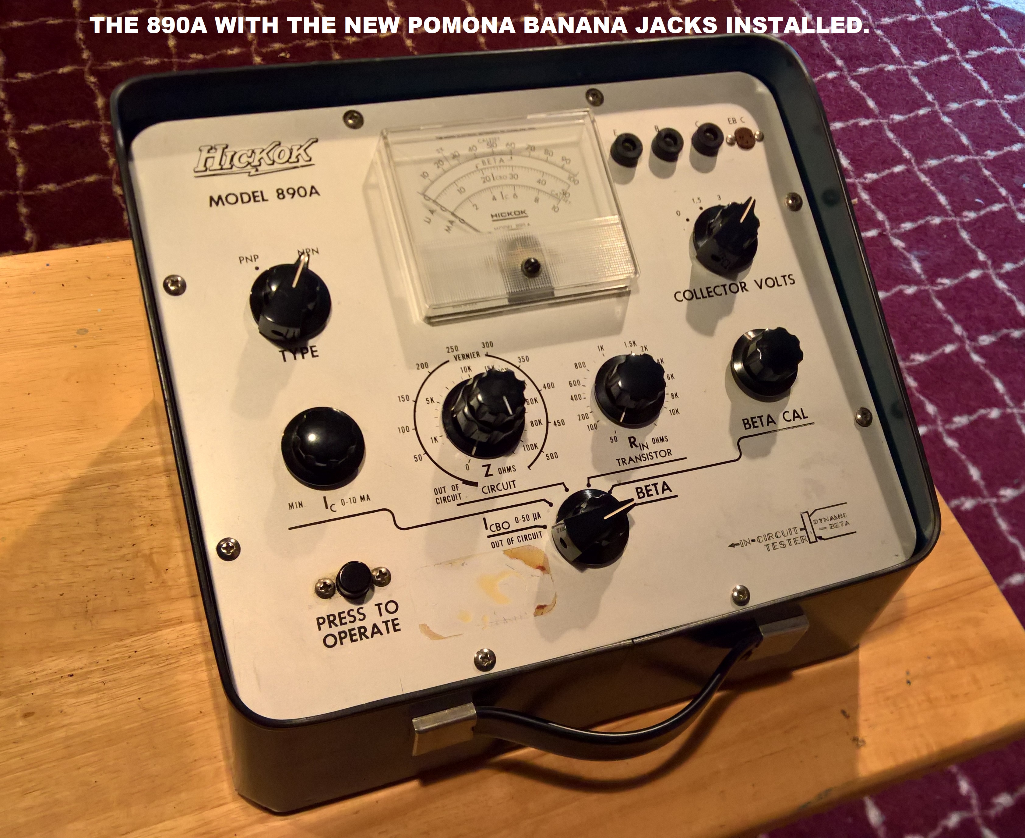
This device uses a bank of "C" cells to provide 1.5, 3, or 4.5 volts for the collector voltage, plus a 22.5 volt "B" battery. The 22.5-volt battery is still available but a modification must be made to the battery holder since the original was a NEDA 420. I plan to restore this to its original condition, and then try to add a mod to closely mimic the 5V, 5A Beta test for power transistors used by the manufacturers. Like the SECO 250, and the EICO 685, this can test devices in or out of circuit.
This tester applies the greatest Vce than any of the others - up to 4.5 volts, but the test current is 0-10 Ma. I plan to change that later.
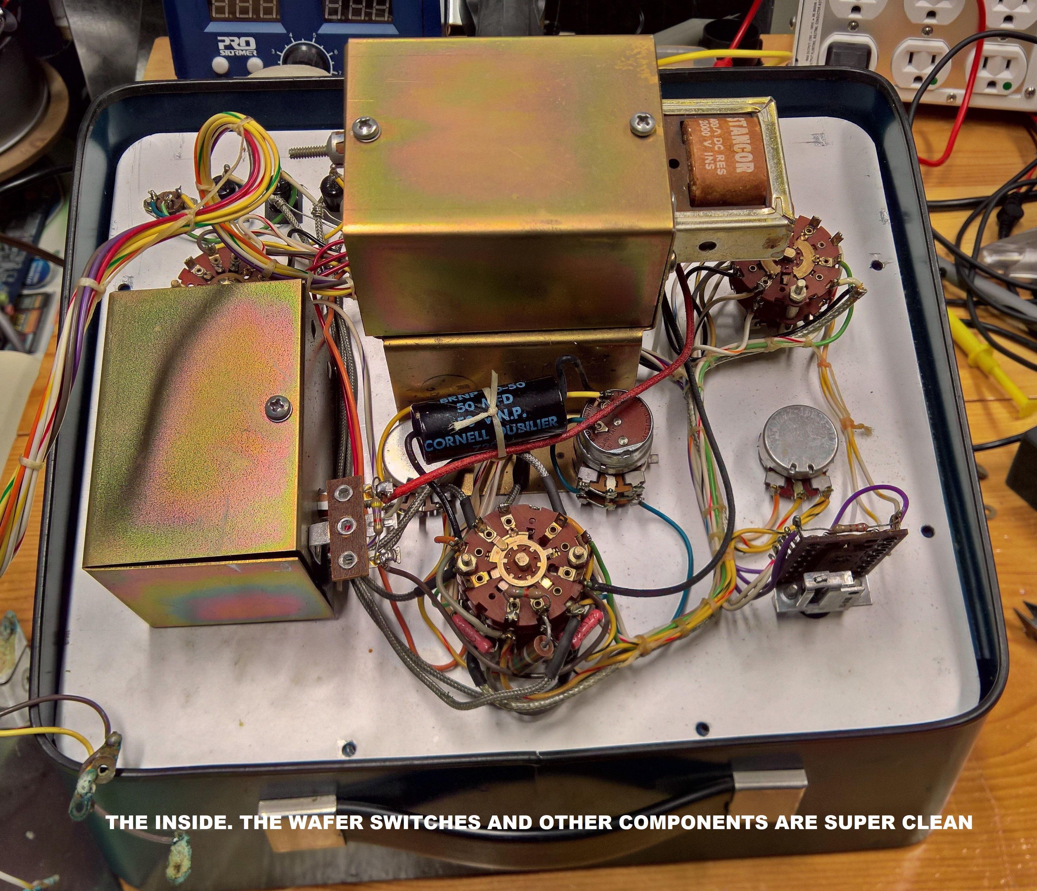
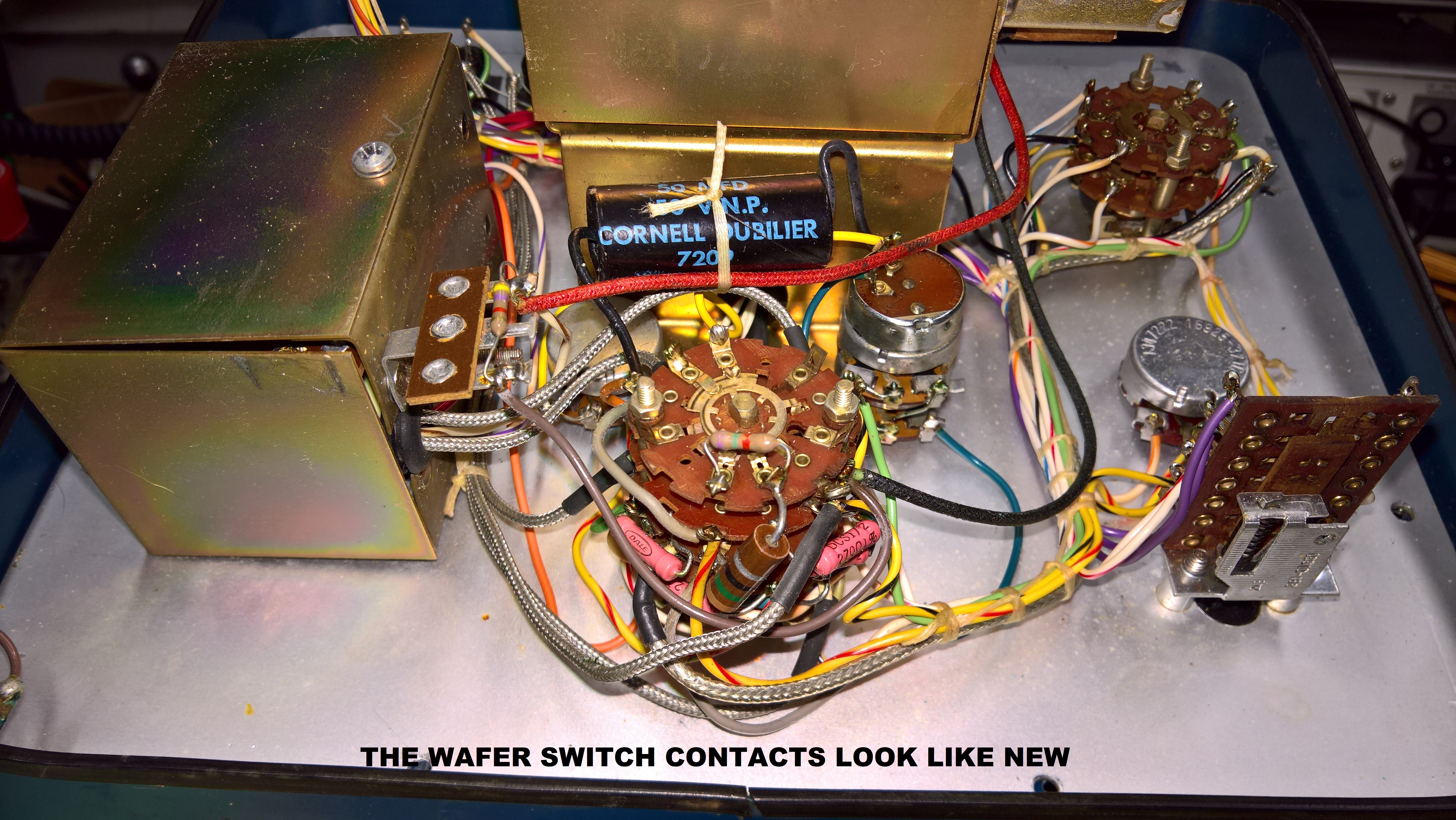
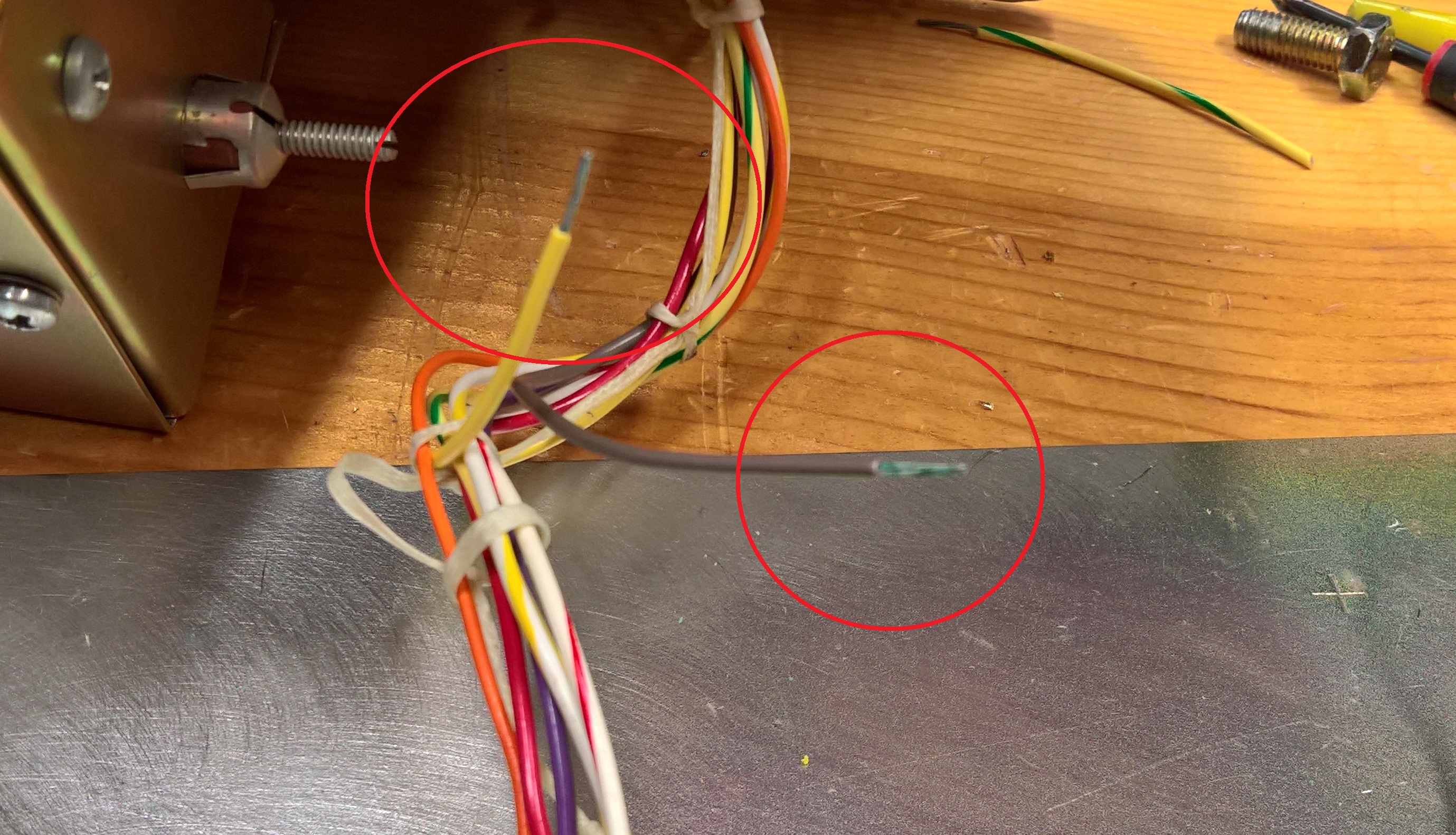
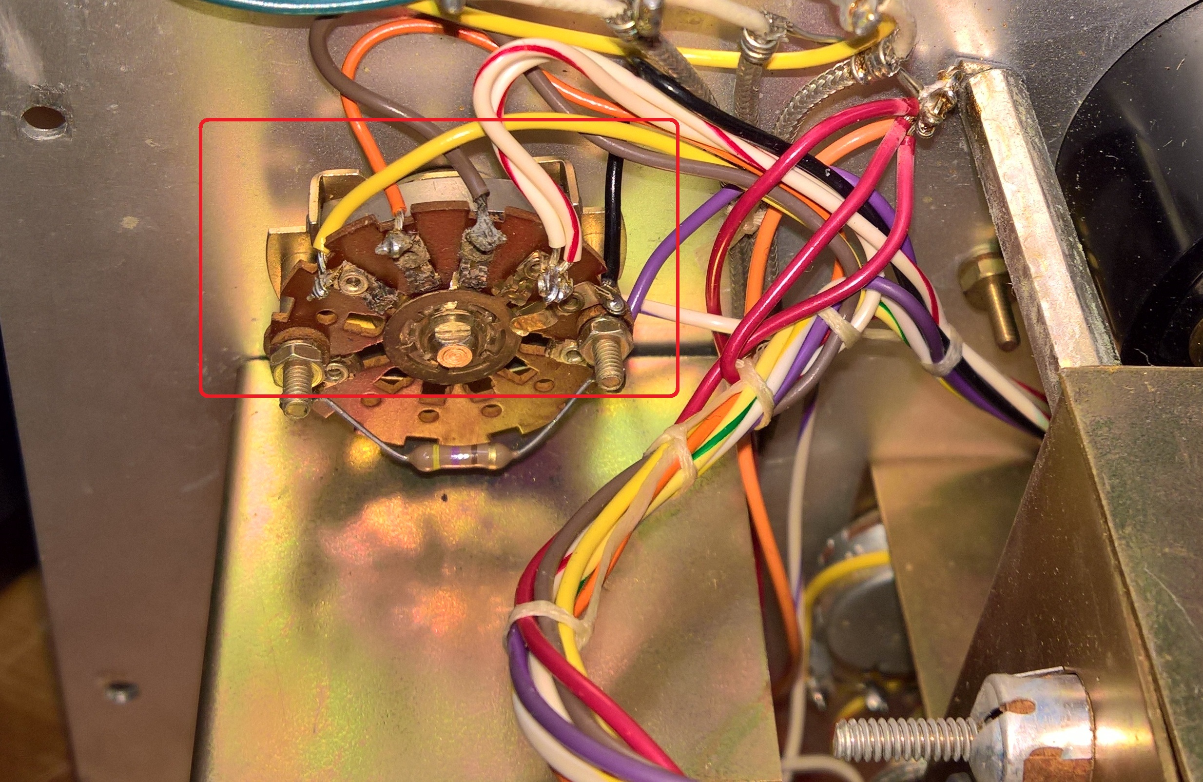
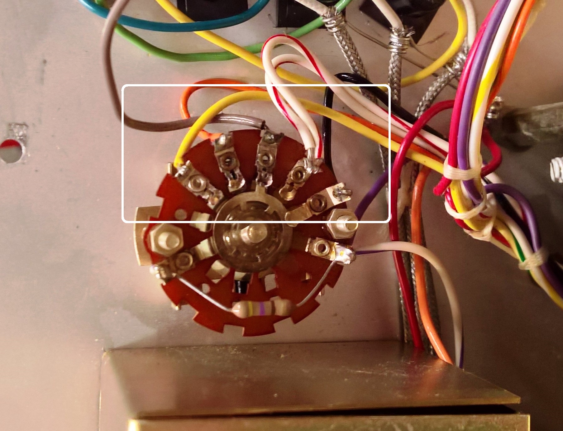
After I opened this unit, I discovered that the battery box was in worse condition than I originally thought. The batteries had corroded and destroyed the C-cell battery box terminals, causing the cables to separate from their positions, and the corrosion migrated up two of the battery wires and actually left a green deposit on the wafer switch. Fortunately, the deposit on the Vce switch came off with DeOxit Gold and a nylon motherboard brush, and the switch works great. That would have been a difficult part to replace.
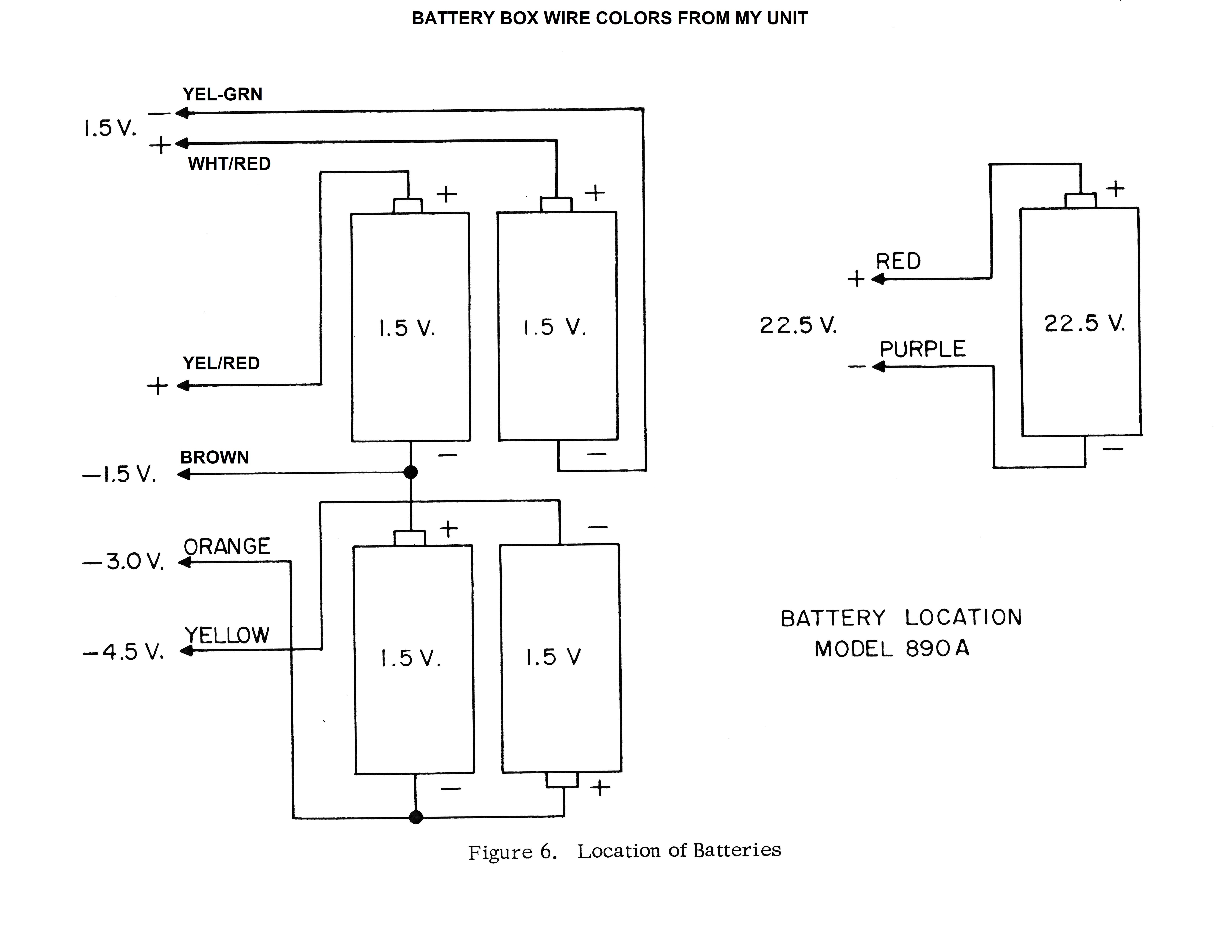
To make matters worse, some of the wire colors didn't match those shown on the schematic, forcing me to spend a bit of time reverse-engineering the battery circuits.
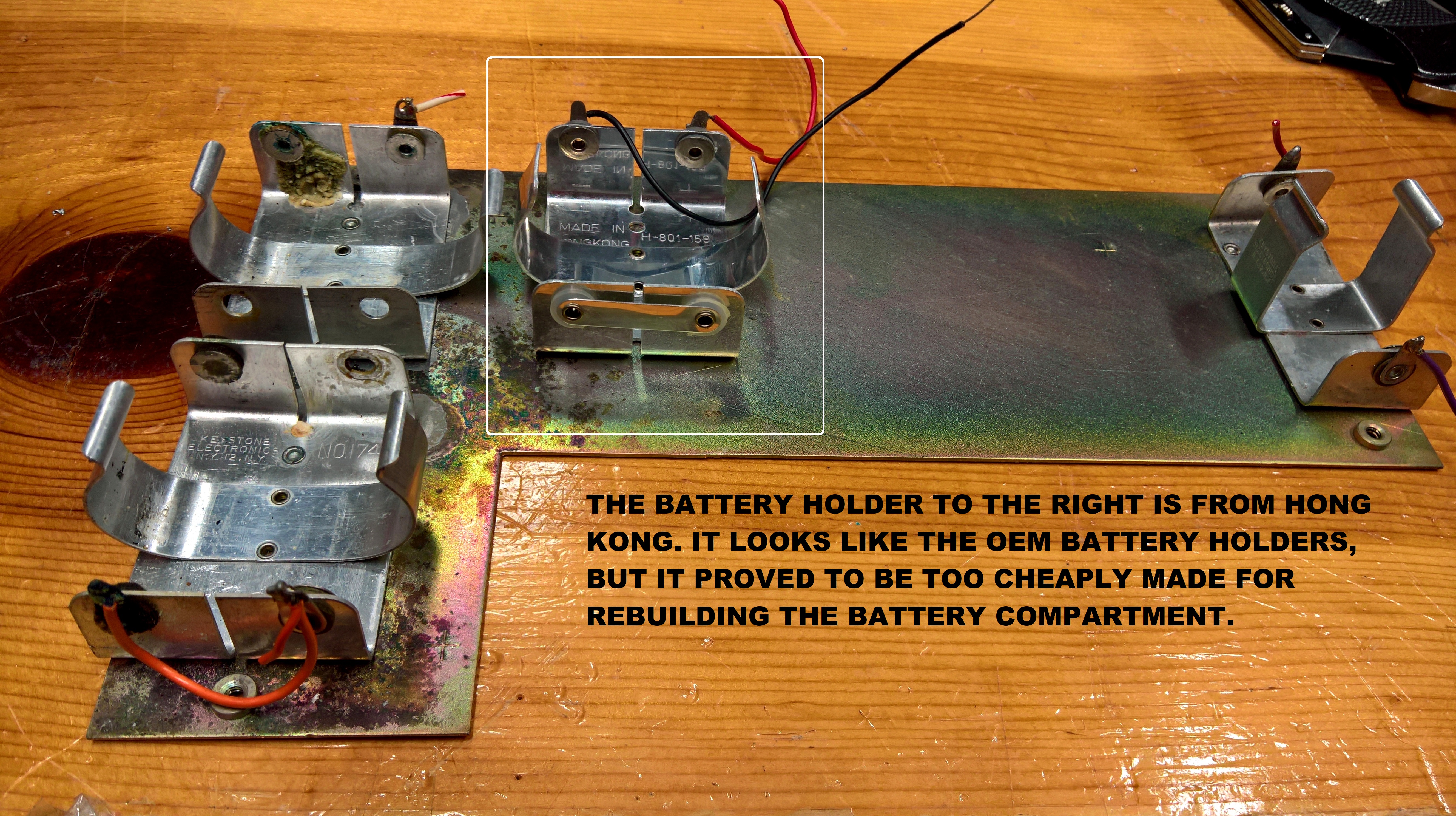
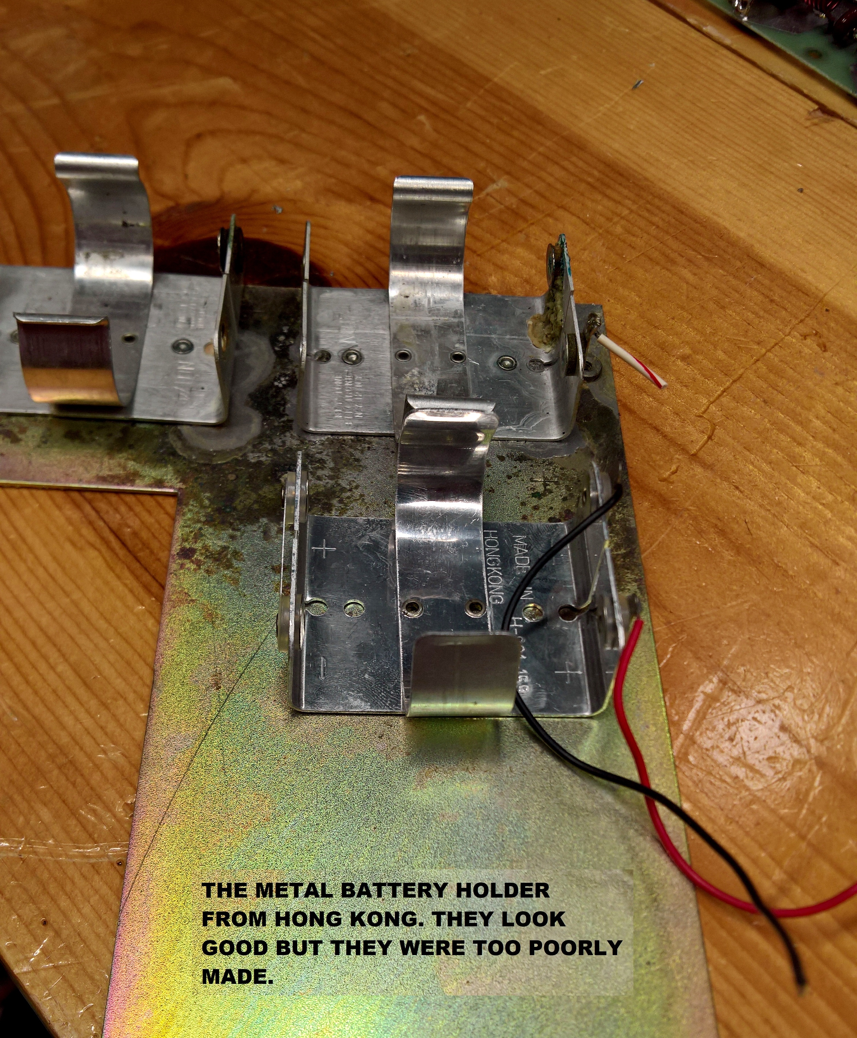
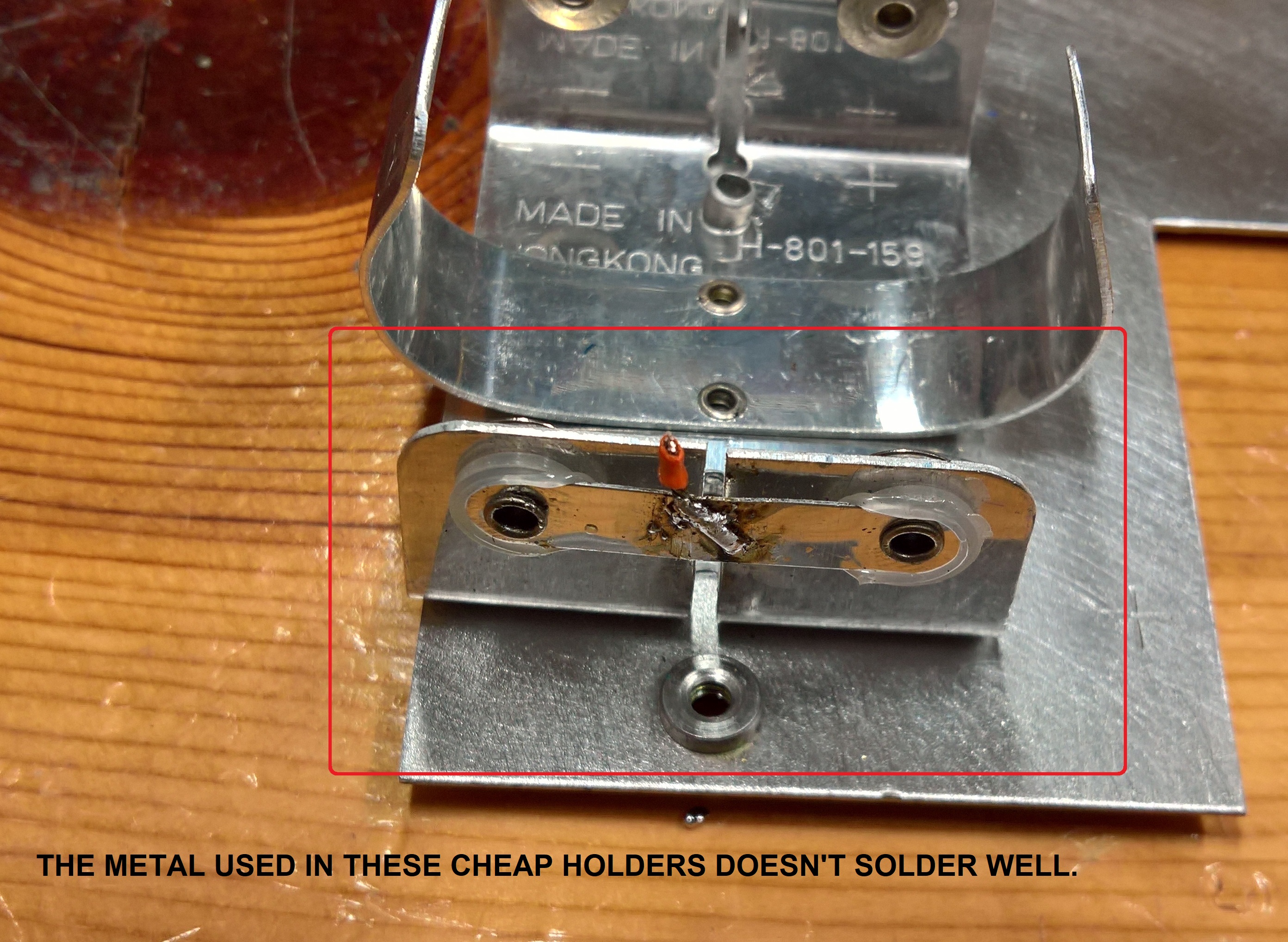
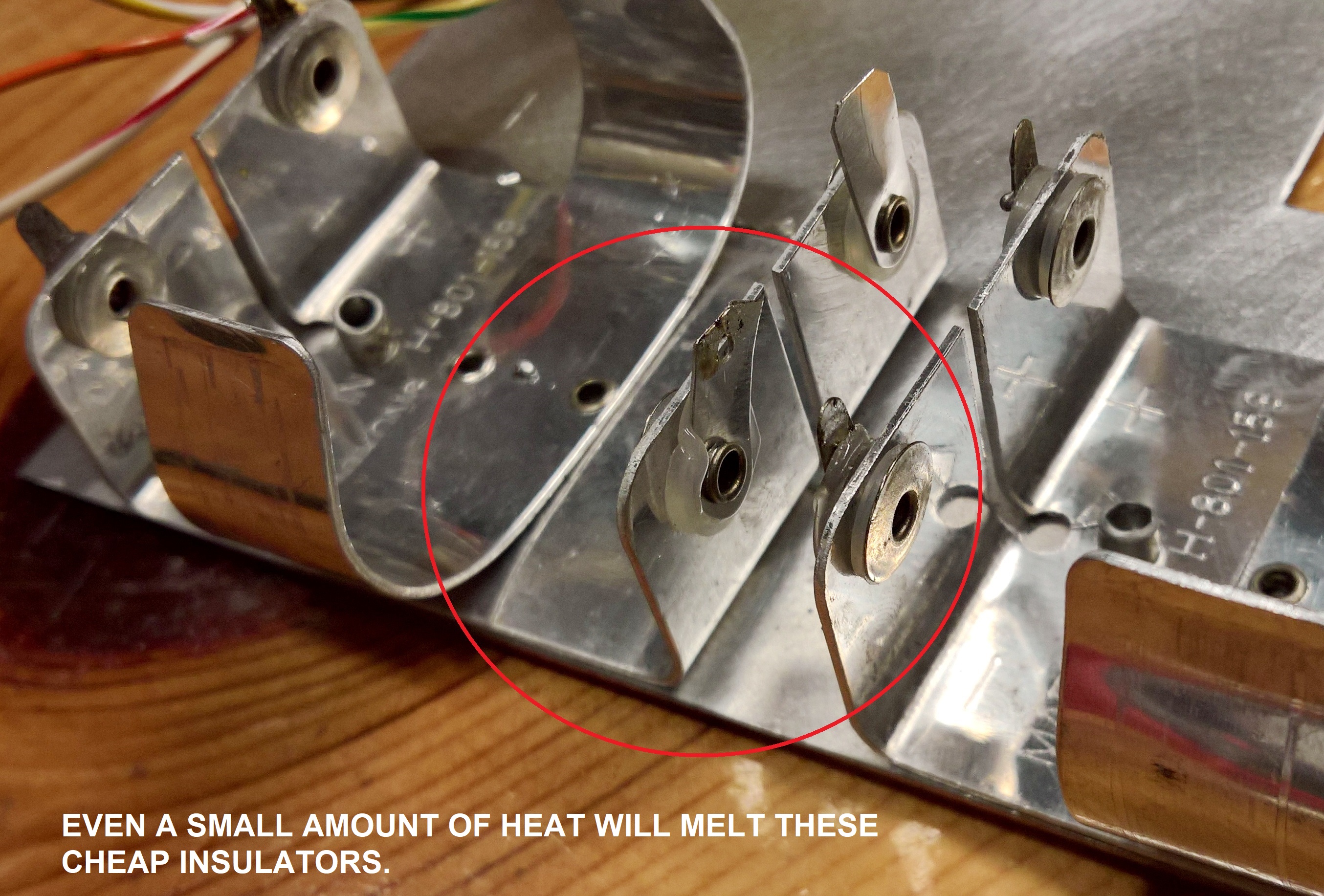
Step one was to find quality replacement battery holders that were a good match to the originals. The ones shown below next to the originals were made in Hong Kong. The metal used for the contacts is cheap, it didn't solder well, and the plastic insulators melted with heat. The originals had fiber washers for insulators. Bottom line: The ones from Hong Kong were a waste of time and money.
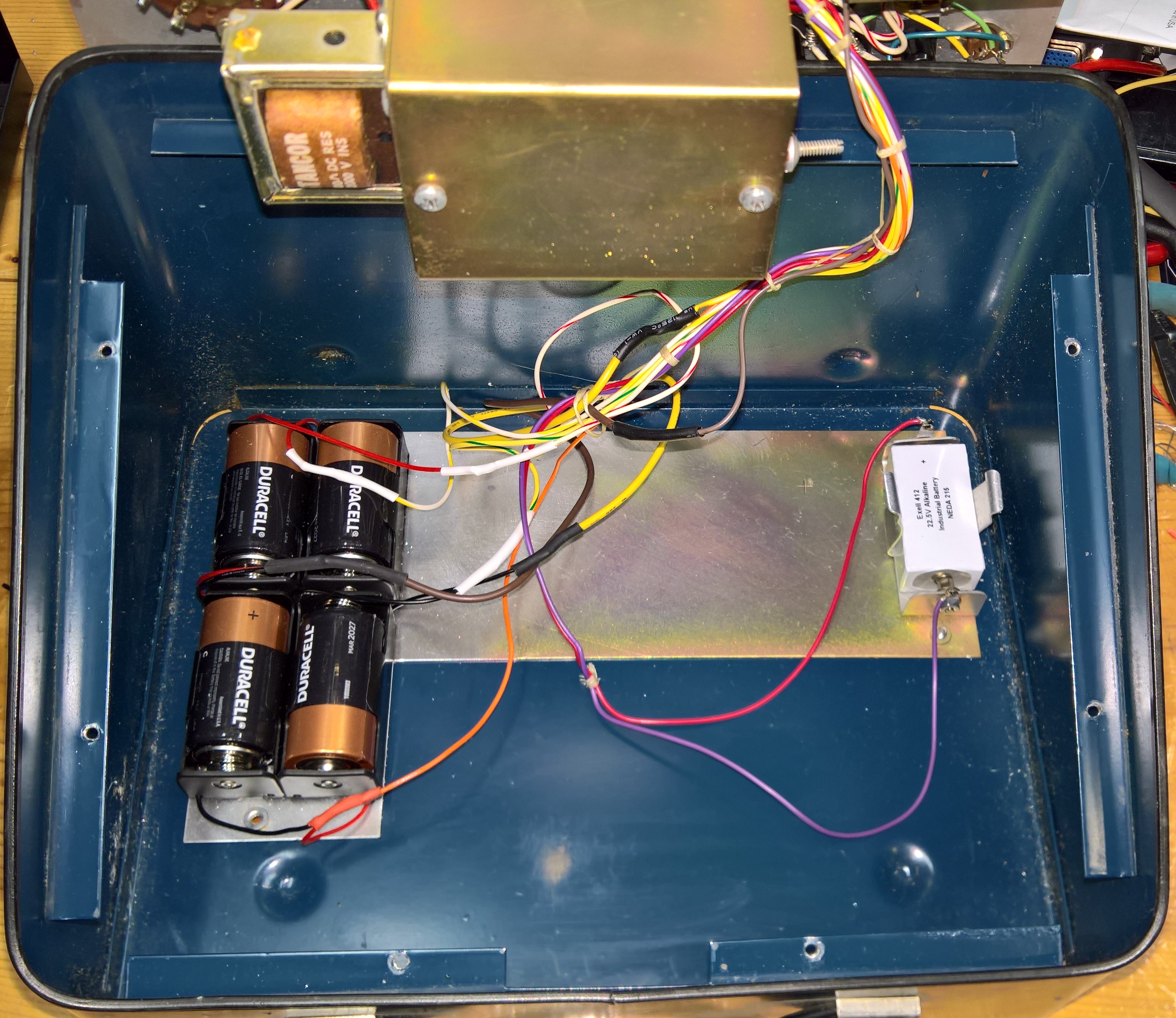
In the end, I was forced to use some plastic C-cell holders that I found on Amazon. I stuck them down for now using 1-inch wide double-side foam tape. My eventual plan is to replace the batteries with an AC power supply capable of delivering the 5 amps that the semiconductor manufacturers claim to use when calculating beta for power tab transistors like the MRF-485.
If you have one of these testers and your battery holders are toast like mine were, you'll need four individual holders, not a single one that holds 4 batteries. The reason will become obvious once you study the schematic and look at the battery box pictures and diagram below. The 890A requires a separate 1.5V feed, a stack of three 1.5V batteries with individual taps, plus the 22.5V B-Battery for the 1KHz oscillator.
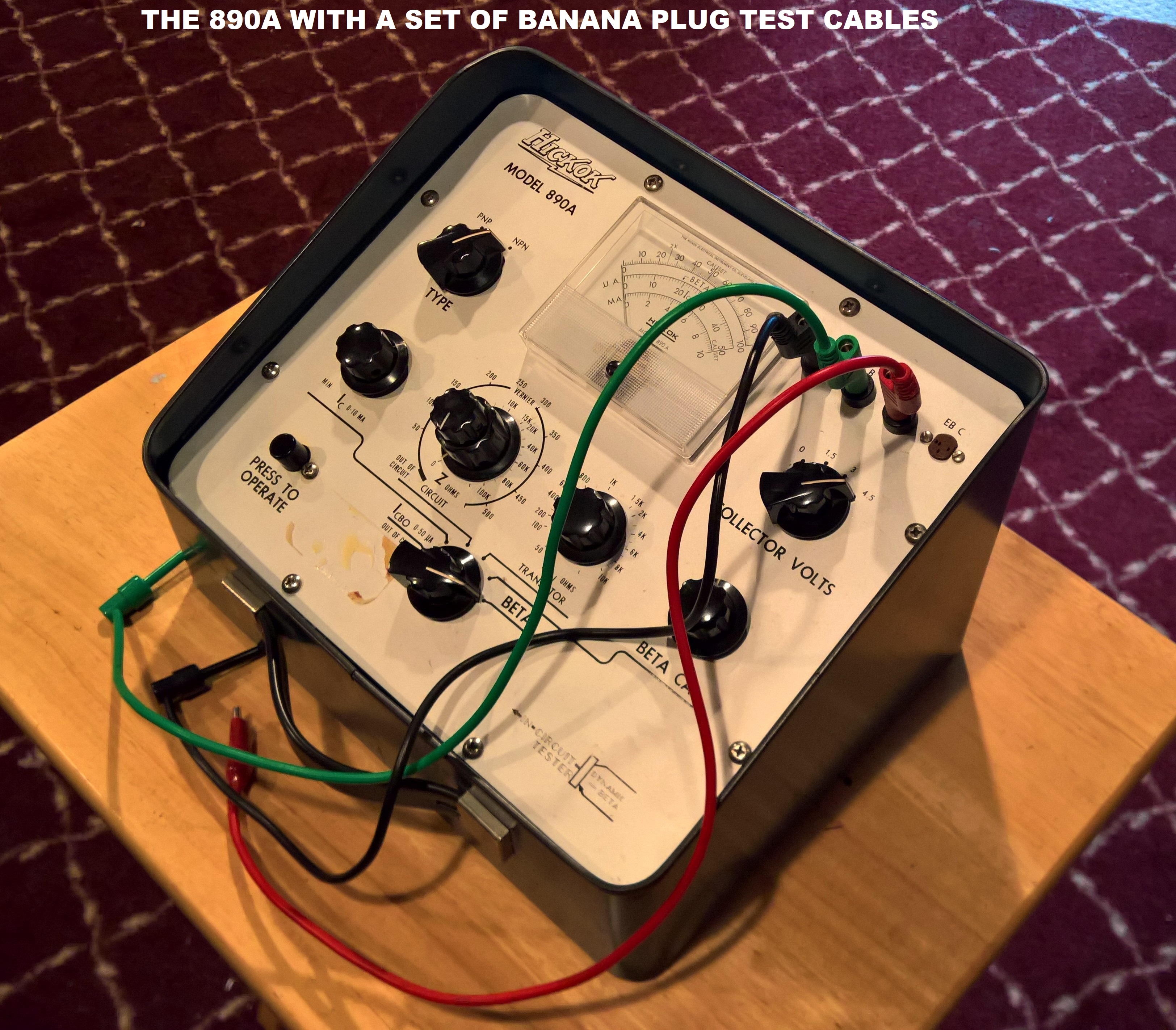
It took awhile, but I figured out the battery wiring and the schematic. My plan is to use it for awhile as designed, use it for some testing and also comparisons to other testers, and create a table of common newer transistors like the MRF-485 drivers and the MRF-422 "pills" used in HAM radios. The 890A was designed as a small-signal transistor tester, but it should handle power transistors as well.
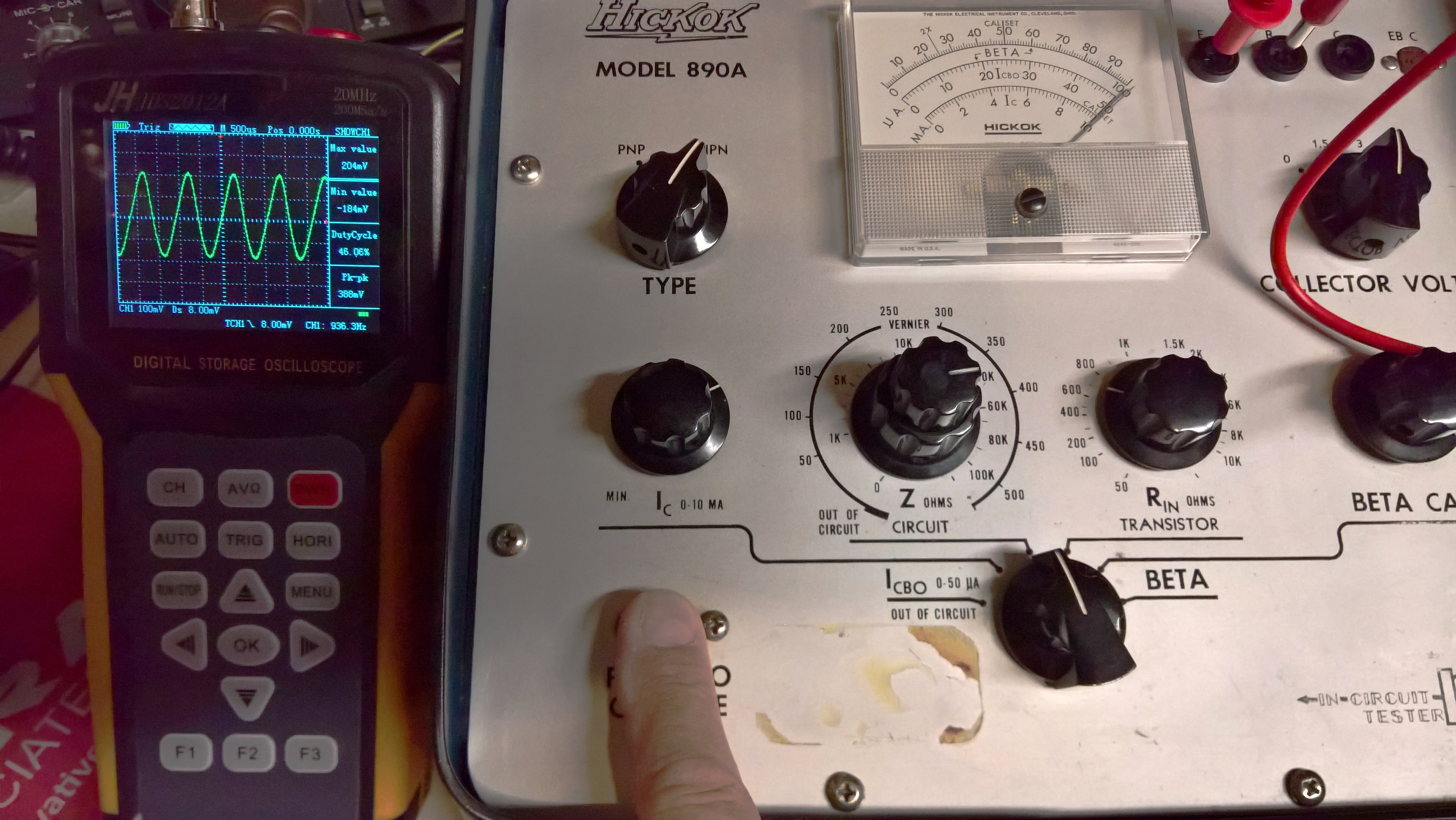
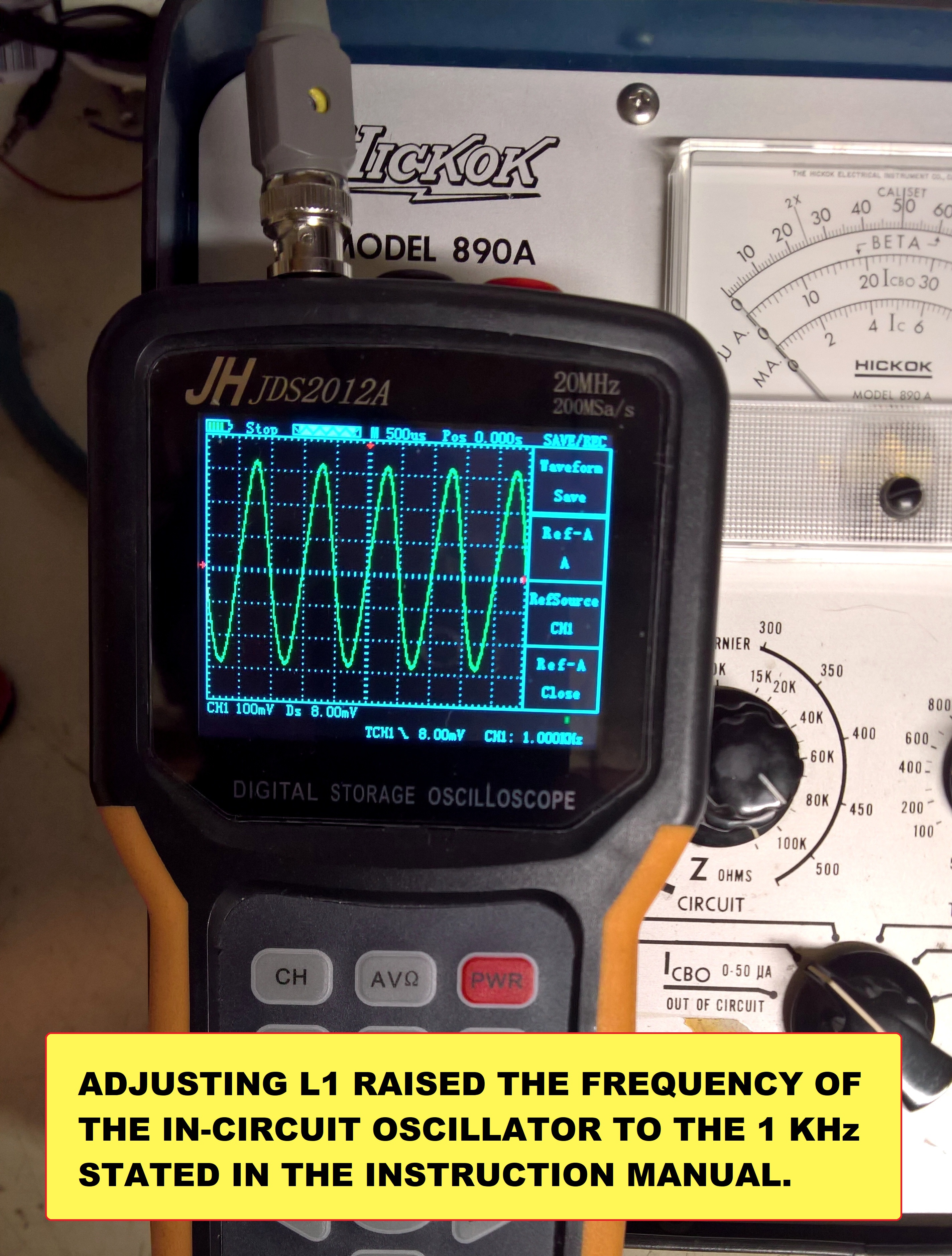
This appears to be working as designed by Hickok now. Even the NPN/PNP switch works. The In-Circuit audio oscillator that generates a 1KHz signal for testing also works. My inexpensive Jinhan scope meter says it's 936.3 Hz. The frequency probably isn't critical, but I decided to raise it to the 1,000 Hz stated in the manual.
I'm really beginning to like the little JinHan Scope Meter you see in these pictures. It's handy and accurate.


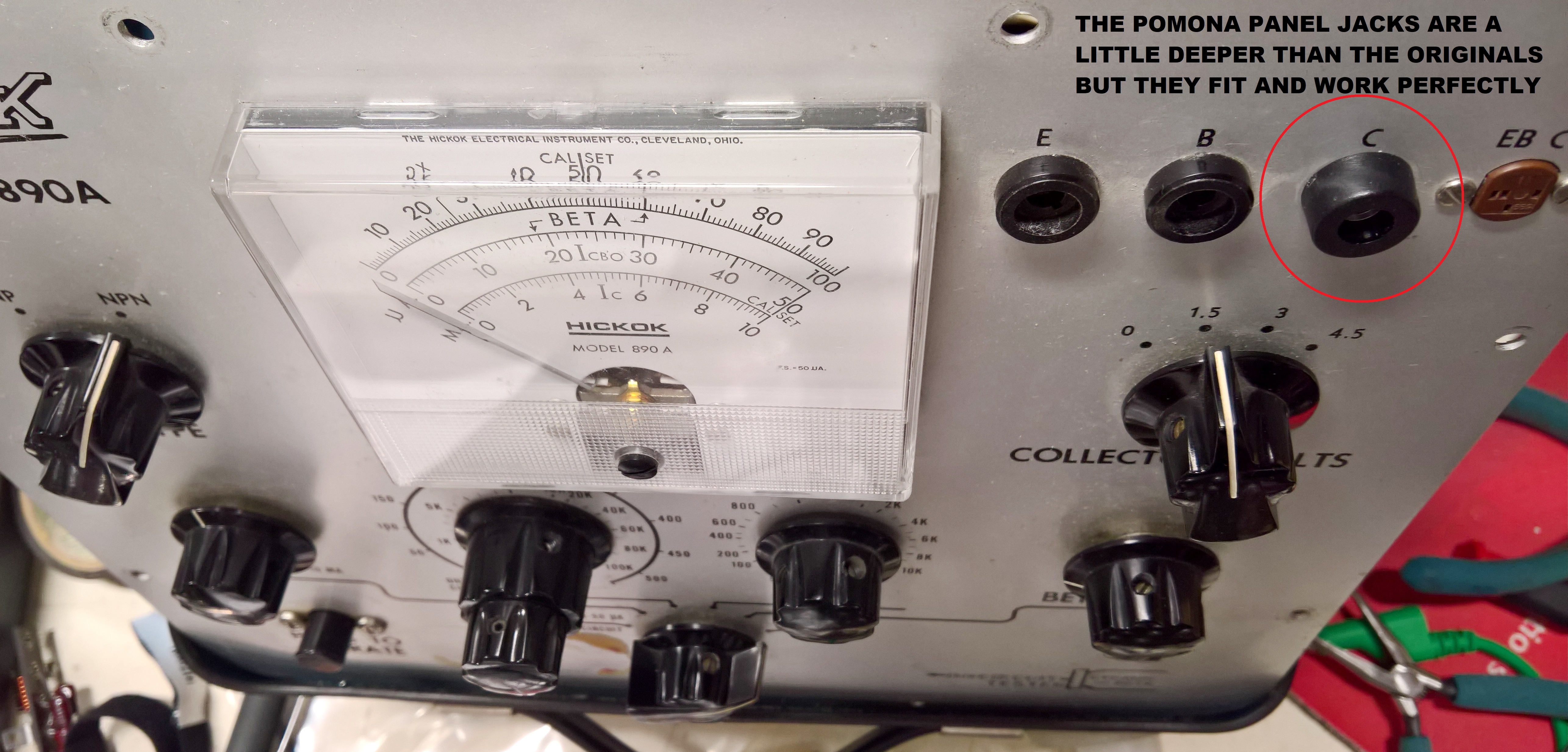
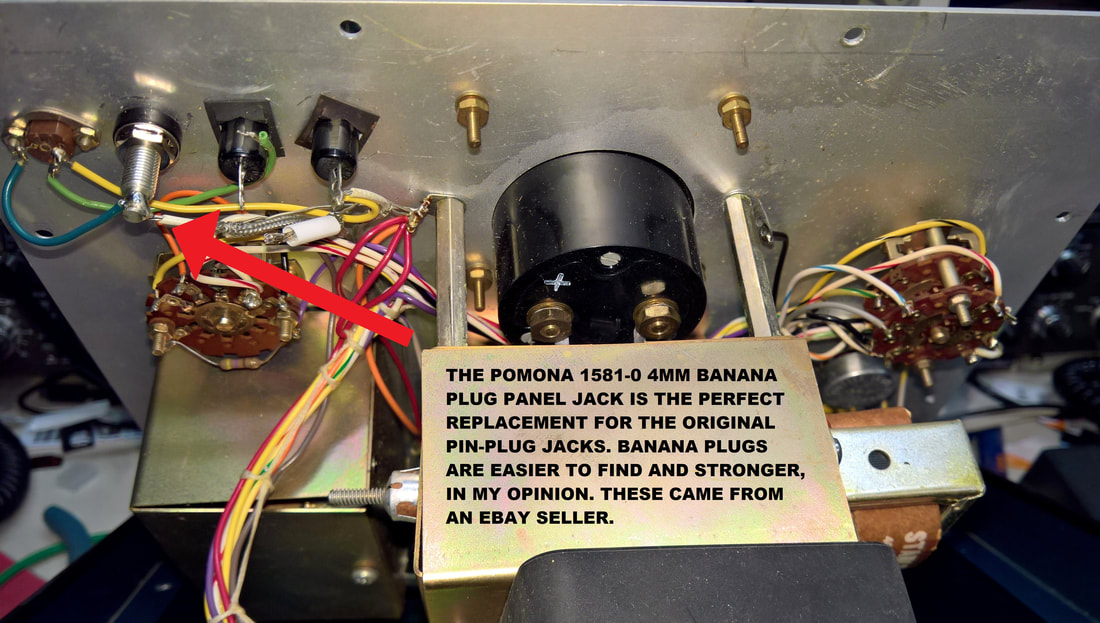


